Page 3956 of 4462

PS-8
POWER STEERING FLUID
Revision: 2006 December 2006 FX35/FX45
POWER STEERING FLUIDPFP:KLF20
Checking Fluid LevelNGS000BT
�Stop engine before performing a fluid level check.
�Ensure that fluid level is between the MAX range and MIN level.
�Because fluid level differs within the HOT range and the COLD
range, check it carefully.
CAUTION:
�Do not overfill the Max level.
�Do not reuse any used power steering fluid.
�Recommended fluid is Genuine NISSAN PSF or equivalent.
Checking Fluid LeakageNGS000BU
Check the hydraulic piping lines for improper attachment and for
leaks, cracks, damage, loose connections, chafing or deterioration.
1. Run engine until fluid temperature reaches 50 to 80 ° C (122 to
176 °F) in reservoir tank. Keep engine speed idle.
2. Turn steering wheel right-to-left several times.
3. Hold steering wheel at each “lock” position for five seconds to check fluid leakage.
CAUTION:
Do not hold steering wheel in a locked position for more
than 10 seconds. (There is the possibility that oil pump may
be damaged.)
4. If fluid leakage at connections is noticed, then loosen flare nut and then retighten. Do not over tighten con- nector as this can damage O-ring, washer and connector.
5. If fluid leakage from oil pump is noticed, check oil pump. Refer to PS-29, "
POWER STEERING OIL
PUMP" .
6. Check steering gear boots for accumulation of fluid indicating a from steering gear.
Air Bleeding Hydraulic SystemNGS000BV
Incomplete air bleeding causes the following. When this happens, bleed air again.
�Generation of air bubbles in reservoir tank.
�Generation of clicking noise in oil pump.
�Excessive buzzing in oil pump.
NOTE:
When vehicle is stationary or while steering wheel is being turned slowly, some noise may be heard from
oil pump or gear. This noise is normal and does not affect any system.
1. Stop engine, and then turn steering wheel fully to right and left several times. CAUTION:
Do not allow steering fluid reservoir tank to go below the low-level line. Check tank frequently and
add fluid as needed.
2. Run engine at idle speed. Turn steering wheel fully to the right and then fully to the left, and keep for about three seconds. Then check whether a fluid leakage has occurred.
3. Repeat the 2nd procedure several times at about three seconds intervals. CAUTION:
Do not hold steering wheel in the locked position more than 10 seconds. (There is the possibility
that oil pump may be damaged.)
4. Check generation of air bubbles and cloud in fluid. HOT : Fluid temperatures from 50 to 80
°C (122 to
176 °F)
COLD : Fluid temperatures from 0 to 30 °C (32 to 86 °F)
SGIA0232J
SGIA0506E
Page 4056 of 4462

RFD-18
REAR FINAL DRIVE ASSEMBLY
Revision: 2006 December 2006 FX35/FX45
Disassembly and AssemblyNDS000CX
COMPONENTS
1. Drive pinion lock nut 2. Companion flange 3. Front oil seal
4. Pinion front bearing 5. Gear carrier 6. Side oil seal
7. Side flange 8. Collapsible spacer 9. Pinion rear bearing
10. Pinion height adjusting washer 11. Drive pinion 12. Side bearing adjusting washer
13. Side bearing 14. Side gear thrust washer 15. Circular clip
16. Side gear 17. Lock pin 18. Pinion mate gear
19. Pinion mate thrust washer 20. Pinion mate shaft 21. Drive gear
22. Differential case 23. Bearing cap 24. Filler plug
25. Gasket 26. Rear cover 27. Drain plug
A: Oil seal lip
B: Screw hole
C: After tightening the bolts to the specified torque, tighten the bolts additionally by turning the bolts 31 to 36 degrees.
Refer to GI-11, "
Components" and the followings for the symbols in the figure.
: Apply multi-purpose grease.
: Apply gear oil.
: Apply anti-corrosion oil.
: Apply Genuine Silicone RTV or equivalent. Refer to
GI-48, "
Recommended Chemical Products and Sealants" .
: Apply Genuine High Strength Thread Locking Sealant or equivalent. Refer to
GI-48, "
Recommended Chemical Prod-
ucts and Sealants" .
PDIA0986E
Page 4074 of 4462

RFD-36
REAR FINAL DRIVE ASSEMBLY
Revision: 2006 December 2006 FX35/FX45
16. Using the drift, drive side oil seals until it becomes flush with the case end.
CAUTION:
�Do not reuse oil seal.
�When installing, do not incline oil seal.
�Apply multi-purpose grease onto oil seal lips, and gear
oil onto the circumference of oil seal.
17. Check and adjust drive gear runout, tooth contact, drive gear to drive pinion backlash, and total preload torque. Refer to RFD-
19, "Drive Gear Runout" , RFD-20, "Tooth Contact" , RFD-21,
"Backlash" , RFD-19, "Total Preload Torque" .
Recheck above items. Readjust the above description, if necessary.
18. Apply sealant to mating surface of rear cover.
�Use Genuine Silicone RTV or equivalent. Refer to GI-48,
"RECOMMENDED CHEMICAL PRODUCTS AND SEAL-
ANTS" .
CAUTION:
Remove old sealant adhering to mounting surfaces. Also
remove any moisture, oil, or foreign material adhering to
application and mounting surfaces.
19. Install rear cover on gear carrier and tighten mounting bolts with the specified torque. Refer to RFD-18, "
COMPONENTS" .
20. Install side flange with the following procedure.
a. Attach the protector to side oil seal.
b. After the side flange is inserted and the serrated part of side gear has engaged the serrated part of flange, remove the pro-
tector.
c. Put a suitable drift on the center of side flange, then drive it until sound changes.
NOTE:
When installation is completed, driving sound of the side flange
turns into a sound which seems to affect the whole final drive.
d. Confirm that the dimension of the side flange installation (Mea- surement A) in the figure comes into the following. Tool number : KV38100200 (J-26233)
SPD560
PDIA0961E
Tool number : KV38107900 (J-39352)
SDIA0822E
Measurement A: 326 - 328 mm (12.83 - 12.91 in)
SDIA1039E
Page 4081 of 4462

REAR SUSPENSION ASSEMBLY RSU-5
C
D
F
G H
I
J
K L
M A
B
RSU
Revision: 2006 December 2006 FX35/FX45
REAR SUSPENSION ASSEMBLYPFP:55020
On-Vehicle Inspection and ServiceNES000HU
Make sure the mounting conditions (looseness, back lash) of each component and component status (wear,
damage) are normal.
INSPECTION OF BALL JOINT END PLAY
Measure axial end play by installing and moving up/down with an
iron pry bar or something similar between suspension arm and axle.
CAUTION:
Be careful not to damage ball joint boot.
SHOCK ABSORBER INSPECTION
Check shock absorber for oil leakage, damage and replace if necessary.
Wheel Alignment InspectionNES000HV
DESCRIPTION
�Measure wheel alignment under unladen conditions. “Unladen conditions” means that fuel, engine cool-
ant, and lubricant are full. Spare tire, jack, hand tools and mats in designated positions.
PRELIMINARY INSPECTION
�Check tires for improper air pressure and wear.
�Check road wheels for runout.
�Check wheel bearing axial end play.
�Check ball joint axial end play of suspension arm.
�Check shock absorber operation.
�Check each mounting point of axle and suspension for looseness and deformation.
�Check each link, arm and member for cracks, deformation, and other damage.
�Check vehicle posture.
GENERAL INFORMATION AND RECOMMENDATIONS
�A four-wheel thrust alignment should be performed.
–This type of alignment is recommended for any NISSAN/INFINITI vehicle.
–The four-wheel “thrust” process helps ensure that the vehicle is properly aligned and the steering wheel is
centered.
–The alignment rack itself should be capable of accepting any NISSAN/INFINITI vehicle.
–The rack should be checked to ensure that it is level.
�Make sure the machine is properly calibrated.
–Your alignment equipment should be regularly calibrated in order to give correct information.
–Check with the manufacturer of your specific equipment for their recommended Service/Calibration
Schedule. Standard value
Axial end play : 0 mm (0 in)
SEIA0245J
Page 4358 of 4462
TF-56
TRANSFER ASSEMBLY
Revision: 2006 December 2006 FX35/FX45
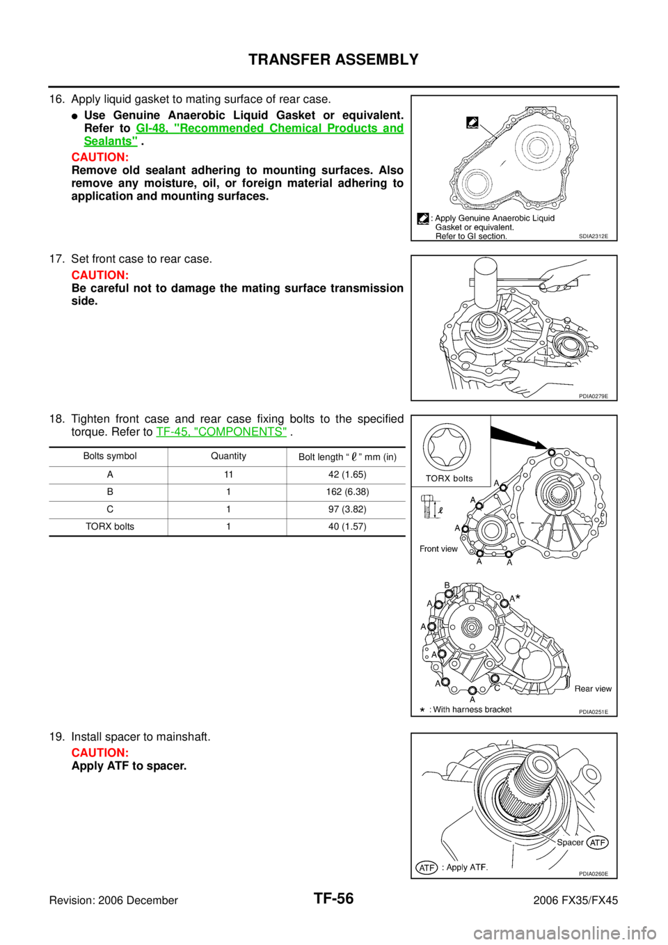
16. Apply liquid gasket to mating surface of rear case.
�Use Genuine Anaerobic Liquid Gasket or equivalent.
Refer to GI-48, "
Recommended Chemical Products and
Sealants" .
CAUTION:
Remove old sealant adhering to mounting surfaces. Also
remove any moisture, oil, or foreign material adhering to
application and mounting surfaces.
17. Set front case to rear case. CAUTION:
Be careful not to damage the mating surface transmission
side.
18. Tighten front case and rear case fixing bolts to the specified torque. Refer to TF-45, "
COMPONENTS" .
19. Install spacer to mainshaft. CAUTION:
Apply ATF to spacer.
SDIA2312E
PDIA0279E
Bolts symbol Quantity Bolt length “ ” mm (in)
A 11 42 (1.65)
B 1 162 (6.38)
C 1 97 (3.82)
TORX bolts 1 40 (1.57)
PDIA0251E
PDIA0260E
Page 4360 of 4462
TF-58
TRANSFER ASSEMBLY
Revision: 2006 December 2006 FX35/FX45
�Use Genuine Silicone RTV or equivalent. Refer to GI-48, "Recommended Chemical Products and
Sealants" .
CAUTION:
Remove old sealant and oil adhering to threads.
26. Set gasket to filler plug. Install it to rear case and tighten to the specified torque. Refer to TF-45, "
COM-
PONENTS" .
CAUTION:
Do not reuse gasket.