Page 3984 of 4462

PS-36
POWER STEERING OIL PUMP
Revision: 2006 December 2006 FX35/FX45
6. Remove snap ring from drive shaft assembly and press out it. CAUTION:
When removing snap ring, be careful not to damage drive
shaft assembly.
7. Using a screwdriver, remove oil seal for body assembly.
8. Remove O-ring from body assembly.
9. Loosen lock nut and remove washer, O-ring, joint then remove connector bolt, O-ring and pull out flow control valve and spring
from body assembly.
CAUTION:
Be careful not to drop and deform the flow control valve.
10. Remove suction pipe from body assembly.
11. Remove O-ring for suction pipe.
INSPECTION AFTER DISASSEMBLY
Body Assembly and Rear Cover Inspection
Check body assembly and the inside of rear cover for damage. If any damage is found, replace with new part
for rear cover and replace with new power steering pump assembly for body assembly.
Cartridge Assembly Inspection
Check cam ring, side plate, rotor and vane for damage. If any damage is found, replace cartridge assembly
with new one.
ASSEMBLY
NOTE:
Fix oil pump in vise as vise occasion demands.
CAUTION:
When retaining drive shaft assembly in a vise, always use copper or aluminum plates between vise
and shaft.
SST010B
SST034A
SGIA0524E
Page 3985 of 4462

POWER STEERING OIL PUMP PS-37
C
D E
F
H I
J
K L
M A
B
PS
Revision: 2006 December 2006 FX35/FX45
1. Apply a coat of Genuine Nissan PSF or equivalent to oil seal lip and to the circumference of oil seal. Using proper tool, such as
hand press machine, install it to body assembly.
NOTE:
Do not reuse oil seal.
2. Apply a coat of Genuine Nissan PSF or equivalent to drive shaft assembly and press drive shaft assembly into body assembly
with suitable tool, then install snap ring.
NOTE:
Do not reuse snap ring.
3. Apply a coat of Genuine Nissan PSF or equivalent to O-ring and Install O-ring into body assembly.
NOTE:
Do not reuse O-ring.
4. Install side plate to body assembly.
5. Install lock pin into lock pin hole, and install cam-ring as shown in the figure.
�When installing cam-ring, turn carved face with a letter (E) of
it to rear cover.
CAUTION:
Do not confuse the assembling direction of cam ring. If
cam ring is installed facing the incorrect direction, it may
cause pump operation malfunction.
6. Install rotor to body assembly.
SST038A
SGIA0422E
SGIA0591E
Page 3986 of 4462
PS-38
POWER STEERING OIL PUMP
Revision: 2006 December 2006 FX35/FX45
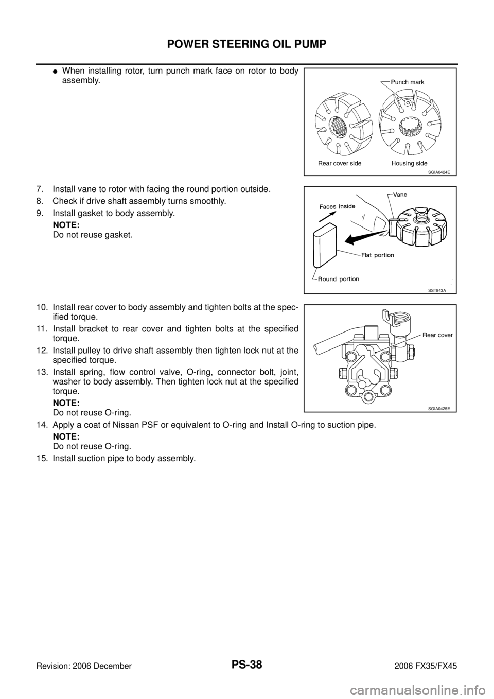
�When installing rotor, turn punch mark face on rotor to body
assembly.
7. Install vane to rotor with facing the round portion outside.
8. Check if drive shaft assembly turns smoothly.
9. Install gasket to body assembly. NOTE:
Do not reuse gasket.
10. Install rear cover to body assembly and tighten bolts at the spec- ified torque.
11. Install bracket to rear cover and tighten bolts at the specified torque.
12. Install pulley to drive shaft assembly then tighten lock nut at the specified torque.
13. Install spring, flow control valve, O-ring, connector bolt, joint, washer to body assembly. Then tighten lock nut at the specified
torque.
NOTE:
Do not reuse O-ring.
14. Apply a coat of Nissan PSF or equivalent to O-ring and Install O-ring to suction pipe. NOTE:
Do not reuse O-ring.
15. Install suction pipe to body assembly.
SGIA0424E
SST843A
SGIA0425E
Page 3999 of 4462

REAR WHEEL HUB AND KNUCKLE RAX-5
C E F
G H
I
J
K L
M A
B
RAX
Revision: 2006 December 2006 FX35/FX45
REAR WHEEL HUB AND KNUCKLEPFP:40202
On-Vehicle Inspection NDS000D1
Make sure the mounting conditions (looseness, back lash) of each component and component status (wear,
damage) are normal.
WHEEL BEARING INSPECTION
With the vehicle raised, inspect the following.
�Move wheel hub in the axial direction by hand. Check that there is no looseness of front wheel bearing.
�Rotate wheel hub and make sure there is no unusual noise or other irregular conditions. If there are any
irregular conditions, replace wheel hub and bearing assembly.
Removal and InstallationNDS000CI
COMPONENTS
REMOVAL
1. Remove tires from vehicle with power tool.
2. Remove cotter pin. Then remove lock nut from drive shaft.
3. Remove brake caliper with power tool. Hang it in a place where it will not interfere with work. Refer to BR-
27, "Removal and Installation of Brake Caliper Assembly" .
NOTE:
�Avoid depressing brake pedal while brake caliper is removed.
4. Remove disc rotor. Refer to BR-27, "
Removal and Installation of Brake Caliper Assembly" .
5. Remove parking cable and parking shoe from back plate. Refer to PB-4, "
Removal and Installation" .
6. Remove wheel sensor from axle. Refer to BRC-55, "
WHEEL SENSORS" .
CAUTION:
Do not pull on wheel sensor harness.
7. Separate drive shaft from wheel hub and bearing assembly by lightly tapping the end with a suitable ham- mer and wood block. If it is hard to separate, use a suitable puller.
8. Remove fixing bolts of wheel hub and bearing assembly with power tool, then remove wheel hub and bearing assembly from axle. Axial end play : 0.05 mm (0.002 in) or less
1. Drive shaft 2. Bushing 3. Axle
4. Back plate 5. Anchor block 6. Wheel bearing
7. Wheel hub 8. Cotter pin
SDIA1481E
Page 4000 of 4462

RAX-6
REAR WHEEL HUB AND KNUCKLE
Revision: 2006 December 2006 FX35/FX45
9. Remove parking brake cable and parking brake shoe from back plate. Refer to PB-6, "PARKING BRAKE
SHOE" and PB-4, "PARKING BRAKE CONTROL" .
10. Remove fixing nuts of anchor block with power tool, then remove anchor block and back plate from axle.
11. Loosen fixing bolts and nuts of front lower link, radius rod, and rear lower link in side of suspension mem- ber.
12. Set jack under rear lower link. Then remove fixing bolt in front lower link side of shock absorber with power tool.
13. Remove bolt and nut in axle side of rear lower link with power tool. Then remove coil spring. Refer to RSU-15, "
REAR LOWER LINK & COIL SPRING" .
14. Remove fixing bolts and nuts in axle side of front lower link, radius rod with power tool.
15. Remove suspension arm and cotter pin at axle, then loosen mounting nut.
16. Use a ball joint remover (suitable tool) to remove suspension arm from axle. Be careful not to damage ball joint boot.
CAUTION:
Tighten temporarily mounting nut to prevent damage to threads and to prevent ball joint remover
(suitable tool) from coming off.
17. Remove axle from vehicle.
INSPECTION AFTER REMOVAL
Check for deformity, cracks and damage on each parts, replace if necessary.
Ball Joint Inspection
Check for boot breakage, axial looseness, and torque of suspension arm ball joint. Refer to RSU-11,
"INSPECTION AFTER REMOVAL" .
INSTALLATION
�Refer to RAX-5, "Removal and Installation" for tightening torque. Install in the reverse order of removal.
NOTE:
Refer to component parts location and do not reuse non-reusable parts.
�Perform final tightening of installation position of suspension links (rubber bushing) under unladen condi-
tions with tires on level ground, Check wheel alignment. Refer to RSU-5, "
Wheel Alignment Inspection" .
�After adjusting wheel alignment, adjust neutral position of steering angle sensor. Refer to BRC-6, "Adjust-
ment of Steering Angle Sensor Neutral Position" .
Page 4001 of 4462

REAR WHEEL HUB AND KNUCKLE RAX-7
C E F
G H
I
J
K L
M A
B
RAX
Revision: 2006 December 2006 FX35/FX45
Disassembly and AssemblyNDS000CJ
DISASSEMBLY
Wheel Bearing
CAUTION:
Do not disassemble if wheel bearing has no trouble.
1. Remove wheel bearing fixing bolts and anchor block fixing nuts, and remove wheel hub and bearing assembly, back plate and anchor block from axle.
2. Using a drift (SST) and a puller (suitable tool), press wheel hub out to remove from wheel bearing.
3. Using a drift (SST) and a puller (suitable tool), press wheel bear- ing outer side inner race out to remove from wheel hub.
Bushing
Using a suitable drift, remove each bushing from axle.
INSPECTION AFTER DISASSEMBLY
Check for deformity, cracks and damage of each parts, replace if necessary.
Wheel Hub
Inspect wheel hub for deformation, cracks, and other damage. If any irregular conditions are found, replace
wheel hub.
Axle
Inspect axle for deformation, cracks, and other damage. If any irregular conditions are found, replace axle.
Back Plate
Inspect back plate for deformation, cracks, and other damage. If any irregular conditions are found, replace
back plate.
SDIA1482E
SDIA1483E
SDIA1484E
Page 4002 of 4462

RAX-8
REAR WHEEL HUB AND KNUCKLE
Revision: 2006 December 2006 FX35/FX45
ASSEMBLY
Bushing
Using a suitable drift to install each bushing onto axle.
Wheel Bearing
1. Press fit a wheel hub into wheel bearing with a drift (SST).
CAUTION:
�Press fit a drift (SST) while holding it against wheel bear-
ing inner side inner race.
�Wheel bearing cannot be reused. Do not attempt to reuse
it.
NOTE:
Final press load guideline 49,033 N (5,000 kg, 11,000 lb)
2. Install back plate and wheel hub and bearing assembly.
3. Install anchor block onto axle.
INSPECTION AFTER ASSEMBLY
1. With wheel bearing pressed into axle housing, apply 49,033 N (5,000 kg, 11,000 lb) to wheel hub and rotate both clockwise and counterclockwise 10 times to minimize resistance.
2. Attach spring scale in the position shown in illustration and pull at a rate of 10 ± 2 rpm to measure rotating torque.
SDIA1485E
SDIA1120E
Rotating torque:
Less than 2.7 N·m (0.28 kg-m, 24 in-lb)
Spring scale reading: Less than 26.6 N (2.7 kg, 5.95 lb)
SDIA1486E
Page 4003 of 4462

REAR DRIVE SHAFT RAX-9
C E F
G H
I
J
K L
M A
B
RAX
Revision: 2006 December 2006 FX35/FX45
REAR DRIVE SHAFTPFP:39600
Removal and InstallationNDS000CK
COMPONENTS
REMOVAL
1. Remove tires from vehicle with power tool.
2. Remove cotter pin. Then remove lock nut from drive shaft.
3. Remove fixing nuts and bolts between side flange and drive shaft with power tool.
4. Using a puller (suitable tool), remove drive shaft from steering knuckle.
CAUTION:
When removing drive shaft, do not apply an excessive
angle to drive shaft joint.Also be careful not to excessively
extend slide joint.
5. Remove drive shaft from axle.
INSPECTION AFTER REMOVAL
�Move joint up/down, left/right, and in the axial direction. Check
for any rough movement or significant looseness.
�Check boot for cracks or other damage, and also for grease
leakage.
�If a trouble is found, disassemble drive shaft, and then replace
with new one.
INSTALLATION
Refer to RAX-9, "Removal and Installation" for tightening torque. Install in the reverse order of removal.
NOTE:
Refer to component parts location and do not reuse non-reusable parts.
1. Side flange 2. Cotter pin
SDIA1487E
SDIA0972J
RAA0030D