Page 4412 of 4462

WW-10
FRONT WIPER AND WASHER SYSTEM
Revision: 2006 December 2006 FX35/FX45
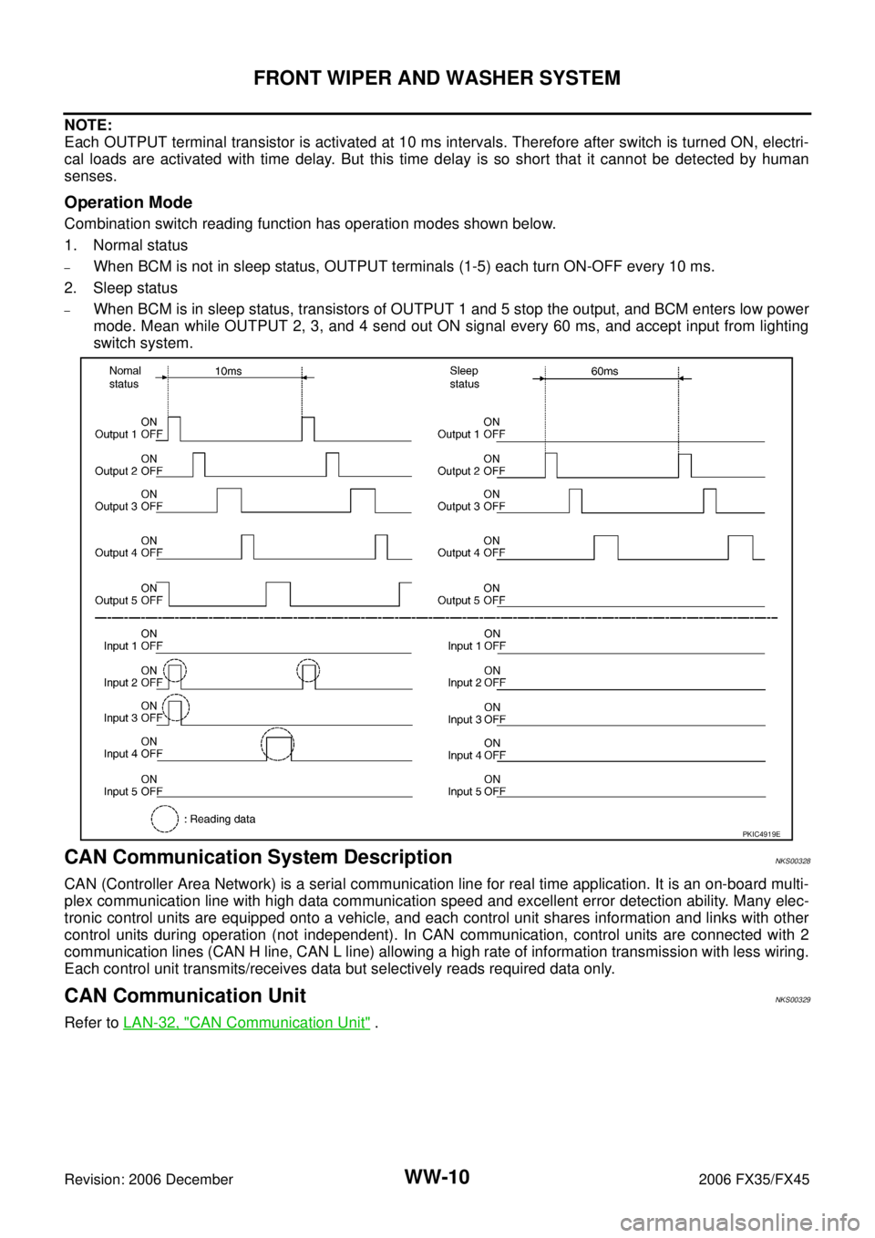
NOTE:
Each OUTPUT terminal transistor is activated at 10 ms intervals. Therefore after switch is turned ON, electri-
cal loads are activated with time delay. But this time delay is so short that it cannot be detected by human
senses.
Operation Mode
Combination switch reading function has operation modes shown below.
1. Normal status
–When BCM is not in sleep status, OUTPUT terminals (1-5) each turn ON-OFF every 10 ms.
2. Sleep status
–When BCM is in sleep status, transistors of OUTPUT 1 and 5 stop the output, and BCM enters low power
mode. Mean while OUTPUT 2, 3, and 4 send out ON signal every 60 ms, and accept input from lighting
switch system.
CAN Communication System DescriptionNKS00328
CAN (Controller Area Network) is a serial communication line for real time application. It is an on-board multi-
plex communication line with high data communication speed and excellent error detection ability. Many elec-
tronic control units are equipped onto a vehicle, and each control unit shares information and links with other
control units during operation (not independent). In CAN communication, control units are connected with 2
communication lines (CAN H line, CAN L line) allowing a high rate of information transmission with less wiring.
Each control unit transmits/receives data but selectively reads required data only.
CAN Communication UnitNKS00329
Refer to LAN-32, "CAN Communication Unit" .
PKIC4919E
Page 4414 of 4462
WW-12
FRONT WIPER AND WASHER SYSTEM
Revision: 2006 December 2006 FX35/FX45
Wiring Diagram — WIPER —NKS0032B
TKWM0663E
Page 4421 of 4462

FRONT WIPER AND WASHER SYSTEM WW-19
C
D E
F
G H
I
J
L
M A
B
WW
Revision: 2006 December 2006 FX35/FX45
How to Proceed With Trouble DiagnosisNKS0032E
1. Confirm the symptoms and customer complaint.
2. Understand operation description and function description. Refer to WW-4, "
System Description" .
3. Perform the Preliminary Check. Refer to WW-19, "
Preliminary Check" .
4. Check symptom and repair or replace the cause of malfunction.
5. Does the front wiper and washer operate normally? If YES, GO TO 6. If NO, GO TO 4.
6. INSPECTION END
Preliminary CheckNKS0032F
CHECK POWER SUPPLY AND GROUND CIRCUIT
1. CHECK FUSE
Check for blown fuses.
Refer to WW-12, "
Wiring Diagram — WIPER —" .
OK or NG
OK >> GO TO 2
NG >> If fuse is blown, be sure to eliminate cause of malfunction before installing new fuse, Refer to PG-
3, "POWER SUPPLY ROUTING CIRCUIT" .
2. CHECK POWER SUPPLY CIRCUIT
1. Turn ignition switch OFF.
2. Disconnect BCM connector.
3. Check voltage between BCM harness connector and ground.
OK or NG
OK >> GO TO 3.
NG >> Repair harness or connector.
3. CHECK GROUND CIRCUIT
Check continuity between BCM harness connector and ground.
OK or NG
OK >> INSPECTION END
NG >> Repair harness or connector.
Unit Power source Fuse and fusible link No.
Front washer pump Ignition switch ON or START 84
Front wiper motor, front wiper relay, front wiper HI relay Battery 73
BCM Battery
M
22
Ignition switch ON or START 1
(+) (-) Ignition switch position
BCM connector Terminal OFF ON M3 38 Ground Approx. 0 V Battery voltage
M4 42 Battery voltage Battery voltage
55 Battery voltage Battery voltage
PKIB5199E
BCM connector Terminal Ground Continuity
M4 49
Ye s
52
PKIB3545E
Page 4443 of 4462
REAR WIPER AND WASHER SYSTEM WW-41
C
D E
F
G H
I
J
L
M A
B
WW
Revision: 2006 December 2006 FX35/FX45
Wiring Diagram — WIP/ R —NKS00335
TKWM4376E
Page 4447 of 4462

REAR WIPER AND WASHER SYSTEM WW-45
C
D E
F
G H
I
J
L
M A
B
WW
Revision: 2006 December 2006 FX35/FX45
How to Proceed With Trouble DiagnosisNKS00337
1. Confirm the symptoms and customer complaint.
2. Understand operation description and function description. Refer to WW-39, "
System Description" .
3. Perform the Preliminary Check. Refer to WW-45, "
Preliminary Check" .
4. Check symptom and repair or replace the cause of malfunction.
5. Does the rear wiper and washer operate normally? If YES, GO TO 6. If NO, GO TO 4.
6. INSPECTION END
Preliminary CheckNKS00338
CHECK POWER SUPPLY AND GROUND CIRCUIT
1. CHECK FUSE
Check for blown fuses.
Refer to WW-41, "
Wiring Diagram — WIP/ R —" .
OK or NG
OK >> GO TO 2.
NG >> If fuse is blown, be sure to eliminate cause of malfunction before installing new fuse, Refer to PG-
3, "POWER SUPPLY ROUTING CIRCUIT" .
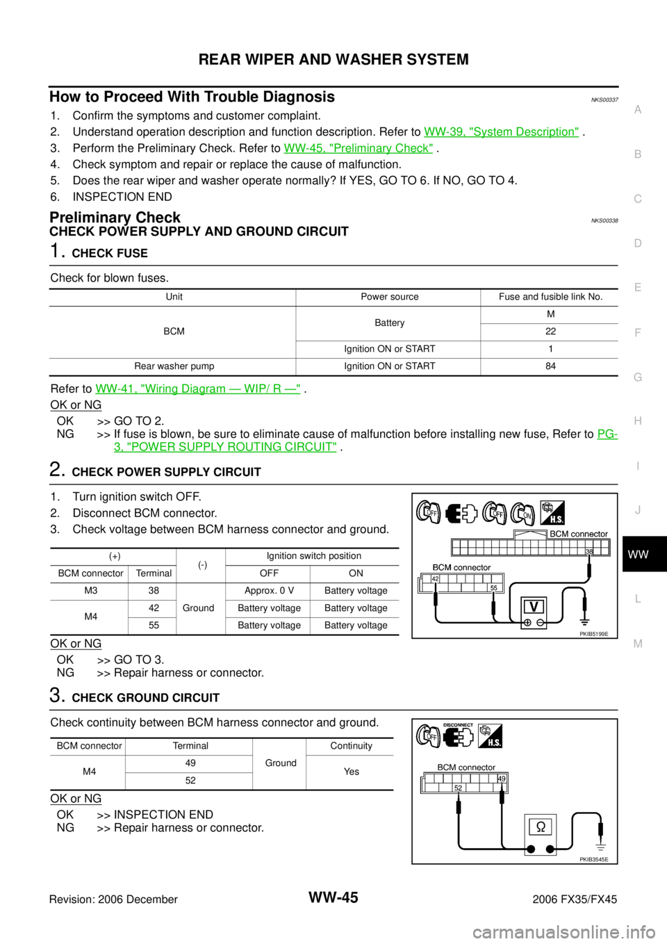
2. CHECK POWER SUPPLY CIRCUIT
1. Turn ignition switch OFF.
2. Disconnect BCM connector.
3. Check voltage between BCM harness connector and ground.
OK or NG
OK >> GO TO 3.
NG >> Repair harness or connector.
3. CHECK GROUND CIRCUIT
Check continuity between BCM harness connector and ground.
OK or NG
OK >> INSPECTION END
NG >> Repair harness or connector.
Unit Power source Fuse and fusible link No.
BCM Battery
M
22
Ignition ON or START 1
Rear washer pump Ignition ON or START 84
(+) (-) Ignition switch position
BCM connector Terminal OFF ON M3 38 Ground Approx. 0 V Battery voltage
M4 42 Battery voltage Battery voltage
55 Battery voltage Battery voltage
PKIB5199E
BCM connector Terminal Ground Continuity
M4 49
Ye s
52
PKIB3545E
Page 4457 of 4462
POWER SOCKET WW-55
C
D E
F
G H
I
J
L
M A
B
WW
Revision: 2006 December 2006 FX35/FX45
POWER SOCKETPFP:253A2
Wiring Diagram — P/SCKT —NKS0033S
TKWM4490E
Page 4460 of 4462
WW-58
HORN
Revision: 2006 December 2006 FX35/FX45
HORNPFP:25610
Wiring Diagram — HORN —NKS0033W
TKWM4378E