Page 3836 of 4462
MA-36
CHASSIS AND BODY MAINTENANCE
Revision: 2006 December 2006 FX35/FX45
Checking Disc BrakeNLS0006Y
ROTOR
Check condition, wear, and damage.
CALIPER
�Check for leakage.
PA D
�Check for wear or damage.
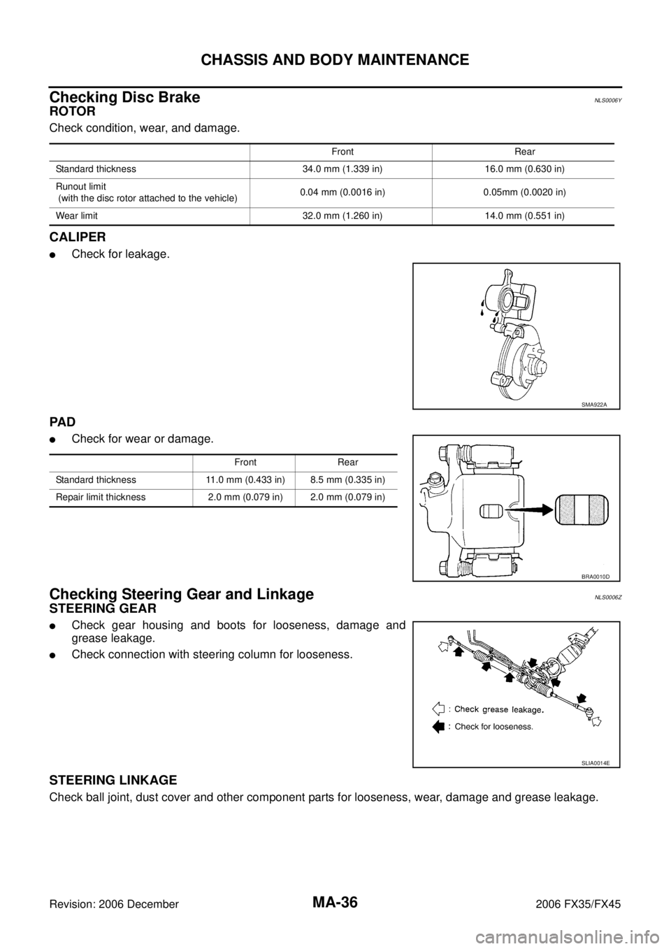
Checking Steering Gear and LinkageNLS0006Z
STEERING GEAR
�Check gear housing and boots for looseness, damage and
grease leakage.
�Check connection with steering column for looseness.
STEERING LINKAGE
Check ball joint, dust cover and other component parts for looseness, wear, damage and grease leakage.
Front Rear
Standard thickness 34.0 mm (1.339 in) 16.0 mm (0.630 in)
Runout limit
(with the disc rotor attached to the vehicle) 0.04 mm (0.0016 in) 0.05mm (0.0020 in)
Wear limit 32.0 mm (1.260 in) 14.0 mm (0.551 in)
SMA922A
Front Rear
Standard thickness 11.0 mm (0.433 in) 8.5 mm (0.335 in)
Repair limit thickness 2.0 mm (0.079 in) 2.0 mm (0.079 in)
BRA0010D
SLIA0014E
Page 3837 of 4462

CHASSIS AND BODY MAINTENANCE MA-37
C
D E
F
G H
I
J
K
M A
B
MA
Revision: 2006 December 2006 FX35/FX45
Checking Power Steering Fluid and LinesNLS00070
Check fluid level in reservoir tank with engine off.
Use “HOT” range at fluid temperatures of 50 to 80 °C (122 to 176 °F)
or “COLD” range at fluid temperatures of 0 to 30 °C (32 to 86 °F).
CAUTION:
�Do not overfill.
�Recommended fluid is Genuine NISSAN PSF or equivalent.
Refer to MA-12, "
RECOMMENDED FLUIDS AND LUBRI-
CANTS"
�Check lines for improper attachment, leaks, cracks, dam-
age, loose connections, chafing and deterioration.
�Check rack boots for accumulation of power steering fluid.
Axle and Suspension PartsNLS00071
Check front and rear axle and suspension parts for excessive play,
cracks, wear or other damage.
�Shake each wheel to check for excessive play.
�Check wheel bearings for smooth operation.
�Check axle and suspension nuts and bolts for looseness.
�Check strut (shock absorber) for oil leakage or other damage.
�Check suspension ball joint for grease leakage and ball joint
dust cover for cracks or other damage.
SST850C
SST851C
SMA525A
SFA392B
Page 3838 of 4462
MA-38
CHASSIS AND BODY MAINTENANCE
Revision: 2006 December 2006 FX35/FX45
Drive ShaftNLS00072
Check boot and drive shaft for cracks, wear, damage and grease
leakage.
Lubricating Locks, Hinges and Hood LatchNLS00073
SFA108A
PIIA7009E
Page 3943 of 4462

REAR PROPELLER SHAFT PR-9
C E F
G H
I
J
K L
M A
B
PR
Revision: 2006 December 2006 FX35/FX45
Removal and InstallationNDS000AY
REMOVAL
1. Move the A/T select lever to N position and release the parking brake.
2. Remove the tunnel stay with power tool. Refer to RSU-5, "
REAR
SUSPENSION ASSEMBLY" .
3. Remove the center muffler with power tool. Refer to EX-3,
"EXHAUST SYSTEM" .
4. Loosen mounting nuts of center bearing mounting brackets with power tool.
CAUTION:
Tighten mounting nuts temporarily.
5. For 2WD models
�Put matching marks on propeller shaft rebro joint with final
drive companion flange.
CAUTION:
For matching mark, use paint. Do not damage propeller
shaft and companion flange.
For AWD models
�Put matching marks on propeller shaft flange yoke with trans-
fer companion flange and on rebro joint with final drive com-
panion flange.
CAUTION:
For matching mark, use paint. Do not damage propeller shaft flange yoke, rebro joint and com-
panion flanges.
6. Remove propeller shaft fixing bolts and nuts.
7. Remove center bearing mounting bracket fixing nuts.
8. Remove propeller shaft.
CAUTION:
If constant velocity joint was bent during propeller shaft assembly removal, installation, or trans-
portation, its boot may be damaged. Wrap boot interference area to metal part with shop cloth or
rubber to protect boot from breakage.
PDIA0744E
PDIA0402E
PDIA0470E
Page 3945 of 4462

REAR PROPELLER SHAFT PR-11
C E F
G H
I
J
K L
M A
B
PR
Revision: 2006 December 2006 FX35/FX45
INSTALLATION
Note the following, and install in the reverse order of removal.
CAUTION:
Avoid damaging the rebro joint boot, protect it with a shop towel or equivalent.
�Align matching marks to install propeller shaft to final drive and transfer (AWD models only) companion
flanges, and then tighten to specified torque. Refer to PR-8, "
Components" .
�Install center bearing mounting bracket (Upper) with its arrow
mark facing forward.
�Adjust position of mounting bracket sliding back and forth to pre-
vent play in thrust direction of center bearing insulator. Install
bracket to vehicle.
�After assembly, perform a driving test to check propeller shaft
vibration. If vibration occurred, separate propeller shaft from
final drive. Reinstall companion flange after rotating it by 60,
120, 180, 240, 300 degrees. Then perform driving test and
check propeller shaft vibration again at each point.
�If propeller shaft or final drive has been replaced, connect them
as follows:
1. Install the propeller shaft while aligning its matching mark A with the matching mark B on the joint as close as possible.
2. Tighten the joint bolts to the specified torque. Refer to PR-8,
"Components" .
CAUTION:
Do not reuse the bolts, nuts and washers.
PDIA0017E
SDIA2049E
Page 3956 of 4462

PS-8
POWER STEERING FLUID
Revision: 2006 December 2006 FX35/FX45
POWER STEERING FLUIDPFP:KLF20
Checking Fluid LevelNGS000BT
�Stop engine before performing a fluid level check.
�Ensure that fluid level is between the MAX range and MIN level.
�Because fluid level differs within the HOT range and the COLD
range, check it carefully.
CAUTION:
�Do not overfill the Max level.
�Do not reuse any used power steering fluid.
�Recommended fluid is Genuine NISSAN PSF or equivalent.
Checking Fluid LeakageNGS000BU
Check the hydraulic piping lines for improper attachment and for
leaks, cracks, damage, loose connections, chafing or deterioration.
1. Run engine until fluid temperature reaches 50 to 80 ° C (122 to
176 °F) in reservoir tank. Keep engine speed idle.
2. Turn steering wheel right-to-left several times.
3. Hold steering wheel at each “lock” position for five seconds to check fluid leakage.
CAUTION:
Do not hold steering wheel in a locked position for more
than 10 seconds. (There is the possibility that oil pump may
be damaged.)
4. If fluid leakage at connections is noticed, then loosen flare nut and then retighten. Do not over tighten con- nector as this can damage O-ring, washer and connector.
5. If fluid leakage from oil pump is noticed, check oil pump. Refer to PS-29, "
POWER STEERING OIL
PUMP" .
6. Check steering gear boots for accumulation of fluid indicating a from steering gear.
Air Bleeding Hydraulic SystemNGS000BV
Incomplete air bleeding causes the following. When this happens, bleed air again.
�Generation of air bubbles in reservoir tank.
�Generation of clicking noise in oil pump.
�Excessive buzzing in oil pump.
NOTE:
When vehicle is stationary or while steering wheel is being turned slowly, some noise may be heard from
oil pump or gear. This noise is normal and does not affect any system.
1. Stop engine, and then turn steering wheel fully to right and left several times. CAUTION:
Do not allow steering fluid reservoir tank to go below the low-level line. Check tank frequently and
add fluid as needed.
2. Run engine at idle speed. Turn steering wheel fully to the right and then fully to the left, and keep for about three seconds. Then check whether a fluid leakage has occurred.
3. Repeat the 2nd procedure several times at about three seconds intervals. CAUTION:
Do not hold steering wheel in the locked position more than 10 seconds. (There is the possibility
that oil pump may be damaged.)
4. Check generation of air bubbles and cloud in fluid. HOT : Fluid temperatures from 50 to 80
°C (122 to
176 °F)
COLD : Fluid temperatures from 0 to 30 °C (32 to 86 °F)
SGIA0232J
SGIA0506E
Page 3965 of 4462

POWER STEERING GEAR AND LINKAGE PS-17
C
D E
F
H I
J
K L
M A
B
PS
Revision: 2006 December 2006 FX35/FX45
POWER STEERING GEAR AND LINKAGEPFP:49001
Removal and InstallationNGS000C3
CAUTION:
Spiral cable may snap due to steering operation if steering column is separated from steering gear
assembly. Therefore fix steering wheel with a string to avoid turns.
REMOVAL
1. Set wheels in the straight-ahead position.
2. Remove tires from vehicle with power tool.
3. Remove undercover with power tool.
4. Confirm slit of lower joint fits with the projection on rear cover cap, furthermore marking position on steering gear assembly
nearly fits with the projection on rear cover cap.
5. Remove cotter pin at steering outer socket, then loosen mount- ing nut.
6. Use a ball joint remover (SST) to remove steering outer socket from steering knuckle. Be careful not to damage ball joint boot.
CAUTION:
Tighten temporarily mounting nut to prevent damage to
threads and to prevent ball joint remover (SST) from com-
ing off.
1. Cotter pin 2. Steering gear assembly 3. Washer
4. Clip
SGIA1432E
SGIA0539E
SDIA1434E
Page 3969 of 4462

POWER STEERING GEAR AND LINKAGE PS-21
C
D E
F
H I
J
K L
M A
B
PS
Revision: 2006 December 2006 FX35/FX45
CAUTION:
�Secure steering gear assembly with a vise, using copper
plates or something similar to prevent it from being dam-
aged. Do not grip cylinder with a vise.
�Before performing disassembly, clean steering gear assem-
bly with kerosene. Be careful not to bring any kerosene into
contact with the discharge and return port connectors.
DISASSEMBLY
1. Remove cylinder tubes from gear housing assembly.
2. Remove rear cover cap from gear housing assembly.
3. Measure adjusting screw height from gear housing assembly, then loosen adjusting screw.
CAUTION:
�Do not turn adjusting screw more than twice.
�Replace steering gear assembly when adjusting screw is
removed or more than twice.
4. Use a rear cover wrench (SST) to remove rear cover from sub- gear assembly.
5. Remove O-ring with a flat-bladed screwdriver, and pull out rear cover.
6. Remove sub-gear assembly from gear housing assembly. CAUTION:
In order to protect oil seal from any damage, pull sub-gear
assembly out straightly.
7. Loosen lock nut of outer socket, and remove outer socket.
8. Remove boot clamps of the small diameter side and the large diameter side, then remove boot.
1. Cotter pin 2. Outer socket 3. Boot clamp
4. Boot 5. Inner socket 6. Boot clamp
7. Gear housing assembly 8. Cylinder tubes 9. Rear cover cap
10. Rear cover 11. O-ring 12. Sub-gear assembly
13. Rack oil seal 14. Rack assembly 15. Rack Teflon ring
16. O-ring 17. End cover assembly
SGIA0544E
SGIA0568E
SGIA0728E
SGIA0508E