2006 INFINITI FX35 instrument panel
[x] Cancel search: instrument panelPage 649 of 4462

AUDIO AV-43
C
D E
F
G H
I
J
L
M A
B
AV
Revision: 2006 December 2006 FX35/FX45
Removal and Installation of Audio UnitNKS003B2
REMOVAL
1. Perform damper lock operation. Refer to AV- 4 2 , "Locking CD Auto-Changer Mechanism" .
2. Remove cluster lid C. Refer to IP-10, "
INSTRUMENT PANEL ASSEMBLY" .
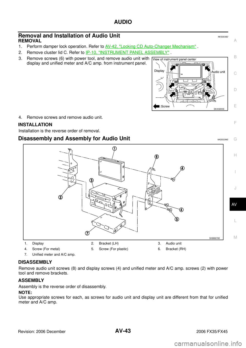
3. Remove screws (6) with power tool, and remove audio unit with display and unified meter and A/C amp. from instrument panel.
4. Remove screws and remove audio unit.
INSTALLATION
Installation is the reverse order of removal.
Disassembly and Assembly for Audio UnitNKS003M0
DISASSEMBLY
Remove audio unit screws (8) and display screws (4) and unified meter and A/C amp. screws (2) with power
tool and remove brackets.
ASSEMBLY
Assembly is the reverse order of disassembly.
NOTE:
Use appropriate screws for each, as screws for audio unit and display unit are different from that for unified
meter and A/C amp.
SKIA5800E
1. Display 2. Bracket (LH) 3. Audio unit
4. Screw (For metal) 5. Screw (For plastic) 6. Bracket (RH)
7. Unified meter and A/C amp.
SKIB8678E
Page 650 of 4462

AV-44
AUDIO
Revision: 2006 December 2006 FX35/FX45
Removal and Installation for A/C and AV SwitchNKS003B4
REMOVAL
1. Remove cluster lid C (1). Refer to IP-10, "INSTRUMENT PANEL ASSEMBLY" .
2. Remove screws (A) and remove A/C and AV switch (2) from cluster lid C (1).
INSTALLATION
Installation is the reverse order of removal.
Removal and Installation for Front Door SpeakerNKS003B5
REMOVAL
1. Remove front door finisher. Refer to EI-35, "Removal and Instal-
lation" .
2. Remove screws (3) and remove front door speaker.
INSTALLATION
Installation is the reverse order of removal.
Removal and Installation for Rear Door SpeakerNKS003B6
REMOVAL
1. Remove rear door finisher. Refer to EI-35, "Removal and Instal-
lation" .
2. Remove screws (3) and remove rear door speaker.
INSTALLATION
Installation is the reverse order of removal.
1. Cluster lid C 2. A/C and AV switch 3. Screws
SKIB8649E
SKIA5803E
SKIA5804E
Page 651 of 4462

AUDIO AV-45
C
D E
F
G H
I
J
L
M A
B
AV
Revision: 2006 December 2006 FX35/FX45
Removal and Installation for Instrument SpeakerNKS003B7
REMOVAL
1. Remove grille from instrument panel.
2. Remove screws (4) and disconnect connector.
3. Remove instrument speaker.
INSTALLATION
Installation is the reverse order of removal.
Removal and Installation for TweeterNKS003B8
REMOVAL
1. Remove rear pillar upper garnish assembly. Refer to EI-44,
"Removal and Installation" .
2. Remove screws (4), and disconnect connector.
3. Remove tweeter.
INSTALLATION
Installation is the reverse order of removal.
Removal and Installation for Woofer (BOSE System)NKS003B9
REMOVAL
1. Open luggage floor board.
2. Remove speaker clamp and harness clip.
3. Disconnect connector.
4. Remove woofer.
CAUTION:
Connectors must be placed in the left side, when installed.
INSTALLATION
Installation is the reverse order of removal.
SKIA5805E
SKIA5806E
SKIA5807E
Page 659 of 4462

ANTENNA AV-53
C
D E
F
G H
I
J
L
M A
B
AV
Revision: 2006 December 2006 FX35/FX45
3. To locate a break, move probe along element. Tester needle will swing abruptly when probe passes the broken point.
Removal and Installation of Roof AntennaNKS003LV
REMOVAL
1. Remove head lining. Refer to EI-42, "HEADLINING" .
2. Remove nut and remove rod and antenna base.
3. Remove instrument panel. Refer to IP-10, "
INSTRUMENT
PANEL ASSEMBLY" .
4. Disassembly antenna feeder (upper) and antenna feeder (lower).
5. Disengaged the clips (7) to separate antenna feeder (upper) from vehicle.
6. Pull off antenna feeder (lower) from audio unit.
7. Disengaged the clips (5) to separate antenna feeder (lower) from vehicle.
INSTALLATION
Installation is the reverse order of removal.
Removal and Installation of Satellite Radio AntennaNKS003LW
Refer to AV- 4 7 , "Removal and Installation of Satellite Radio Antenna" .
SEL253I
PKIA2463E
SKIA5821E
Page 698 of 4462

AV-92
INTEGRATED DISPLAY SYSTEM
Revision: 2006 December 2006 FX35/FX45
Example of Symptoms Possible No MalfunctionNKS003JT
For system operation information, refer to Owner's Manual.
DISPLAY
Removal and Installation of DisplayNKS003LI
Refer to AV- 4 3 , "Disassembly and Assembly for Audio Unit" .
Removal and Installation of Display Control UnitNKS003LZ
REMOVAL
1. Remove instrument passenger lower panel. Refer to IP-10,
"INSTRUMENT PANEL ASSEMBLY" .
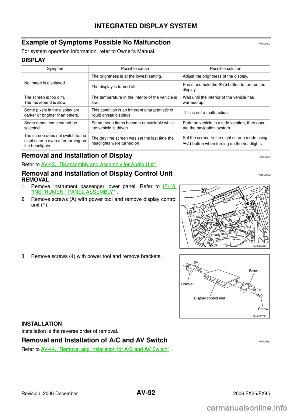
2. Remove screws (A) with power tool and remove display control unit (1).
3. Remove screws (4) with power tool and remove brackets.
INSTALLATION
Installation is the reverse order of removal.
Removal and Installation of A/C and AV SwitchNKS003LJ
Refer to AV- 4 4 , "Removal and Installation for A/C and AV Switch" .
Symptom Possible cause Possible solution
No image is displayed. The brightness is at the lowest setting. Adjust the brightness of the display.
The display is turned off. Press and hold the button to turn on the
display.
The screen is too dim.
The movement is slow. The temperature in the interior of the vehicle is
low. Wait until the interior of the vehicle has
warmed up.
Some pixels in the display are
darker or brighter than others. This condition is an inherent characteristic of
liquid crystal displays. This is not a malfunction.
Some menu items cannot be
selected. Some menu items become unavailable while
the vehicle is driven. Park the vehicle in a safe location, then oper-
ate the navigation system.
The screen does not switch to the
night screen even after turning on
the headlights. The daytime screen was set the last time the
headlights were turned on. Set the screen to the night screen mode using
button when turning on the headlights.
SKIB8667E
SKIA5826E
Page 778 of 4462

AV-172
INFINITI MOBILE ENTERTAINMENT SYSTEM
Revision: 2006 December 2006 FX35/FX45
Removal and Installation for DVD PlayerNKS003ED
REMOVAL
1. Remove center console. Refer to IP-10, "INSTRUMENT PANEL ASSEMBLY" .
2. Remove center console rear finisher. Refer to IP-12, "
(H) Center Console" .
3. Remove screws (2) with power tool and remove DVD player.
4. Remove screws (4) with power tool and remove brackets.
INSTALLATION
Installation is the reverse order of removal.
Removal and Installation for DVD Display UnitNKS003EE
REMOVAL
1. Insert cloth-covered driver into gaps between rear display cover and head lining, and remove rear display cover.
2. Press pawl on rear side and remove inner cover.
SKIA5810E
SKIA5811E
SKIA5812E
SKIA5813E
Page 797 of 4462

TELEPHONE AV-191
C
D E
F
G H
I
J
L
M A
B
AV
Revision: 2006 December 2006 FX35/FX45
Removal and Installation of TEL Adapter UnitNKS003IV
REMOVAL
1. Remove instrument passenger lower panel. Refer to IP-10, "INSTRUMENT PANEL ASSEMBLY" .
2. Remove screws (A) with power tool and remove display control unit (1)and TEL adapter unit (2).
3. Remove TEL adapter unit screws, display control unit screws, and remove brackets.
INSTALLATION
Installation is the reverse order of removal.
Removal and Installation for TEL AntennaNKS003IW
REMOVAL
1. Remove TEL adapter unit, display control unit. Refer to AV- 1 9 1 , "Removal and Installation of TEL Adapter
Unit" .
2. Remove screws (A) and remove TEL antenna (1) from bracket.
INSTALLATION
Installation is the reverse order of removal.
Removal and Installation of MicrophoneNKS003IX
REMOVAL
1. Remove roof console. Refer to EI-42, "HEADLINING" .
2. Remove screws (A) and remove microphone (1) from roof con- sole.
INSTALLATION
Installation is the reverse order of removal.
SKIB8667E
SKIB8669E
SKIB8670E
Page 815 of 4462

BL-1
BODY, LOCK & SECURITY SYSTEM
I BODY
CONTENTS
C
D E
F
G H
J
K L
M
SECTION BL
A
B
BL
Revision: 2006 December 2006 FX35/FX45
BODY, LOCK & SECURITY SYSTEM
PRECAUTIONS ..................................................... ..... 5
Precautions for Supplemental Restraint System
(SRS) “AIR BAG” and “SEAT BELT PRE-TEN-
SIONER” ............................................................. ..... 5
Precautions Necessary for Steering Wheel Rotation
After Battery Disconnect ..................................... ..... 5
OPERATION PROCEDURE ............................ ..... 5
Precautions for Work ........................................... ..... 5
PREPARATION ...................................................... ..... 6
Special Service Tools .......................................... ..... 6
Commercial Service Tools ................................... ..... 6
SQUEAK AND RATTLE TROUBLE DIAGNOSIS . ..... 7
Work Flow ........................................................... ..... 7
CUSTOMER INTERVIEW ................................ ..... 7
DUPLICATE THE NOISE AND TEST DRIVE .. ..... 8
CHECK RELATED SERVICE BULLETINS ...... ..... 8
LOCATE THE NOISE AND IDENTIFY THE
ROOT CAUSE ................................................. ..... 8
REPAIR THE CAUSE ...................................... ..... 8
CONFIRM THE REPAIR .................................. ..... 9
Generic Squeak and Rattle Troubleshooting ...... ..... 9
INSTRUMENT PANEL ..................................... ..... 9
CENTER CONSOLE ........................................ ..... 9
DOORS ............................................................ ..... 9
TRUNK ............................................................. ... 10
SUNROOF/HEADLINING ................................ ... 10
SEATS .............................................................. ... 10
UNDERHOOD .................................................. ... 10
Diagnostic Worksheet ......................................... .... 11
HOOD .................................................................... ... 13
Fitting Adjustment ............................................... ... 13
LONGITUDINAL AND LATERAL CLEARANCE
ADJUSTMENT ................................................. ... 13
FRONT END HEIGHT ADJUSTMENT ............ ... 13
SURFACE HEIGHT ADJUSTMENT ................ ... 13
Removal and Installation of Hood Assembly ....... ... 14
REMOVAL ........................................................ ... 15
INSTALLATION ................................................ ... 15
Removal and Installation of Hood Lock Control .. ... 15
REMOVAL ........................................................ ... 15 INSTALLATION ................................................
... 16
Hood Lock Control Inspection ............................. ... 16
RADIATOR CORE SUPPORT ............................... ... 18
Removal and Installation ..................................... ... 18
REMOVAL ........................................................ ... 18
INSTALLATION ................................................ ... 19
FRONT FENDER ................................................... ... 20
Removal and Installation ..................................... ... 20
REMOVAL ........................................................ ... 20
INSTALLATION ................................................ ... 20
POWER DOOR LOCK SYSTEM ........................... ... 21
Component Parts and Harness Connector Location ... 21
System Description .............................................. ... 22
OUTLINE .......................................................... ... 23
CAN Communication System Description ........... ... 24
CAN Communication Unit .................................... ... 24
Schematic/With Intelligent Key ............................ ... 25
Wiring Diagram — D/LOCK —/With Intelligent Key ... 26
Schematic/Without Intelligent Key ....................... ... 31
Wiring Diagram — D/LOCK —/Without Intelligent
Key ...................................................................... ... 32
Terminals and Reference Value for BCM ............ ... 36
Terminals and Reference Value for Intelligent Key
Unit (With Intelligent Key System) ....................... ... 36
Work Flow ............................................................ ... 37
CONSULT-II Function (BCM) .............................. ... 37
CONSULT-II START PROCEDURE ................. ... 37
CONSULT-II APPLICATION ITEMS ................. ... 37
Trouble Diagnosis Chart by Symptom ................. ... 38
Check BCM Power Supply and Ground Circuit ... ... 39
Check Door Switch .............................................. ... 40
CHECK DOOR SWITCH (EXCEPT BACK DOOR
SWITCH) .......................................................... ... 40
CHECK BACK DOOR SWITCH ....................... ... 42
Check Key Switch ................................................ ... 44
Check Door Lock and Unlock Switch .................. ... 46
Check Door Lock Actuator (Driver Side) ............. ... 48
Check Door Lock Actuator (Passenger Side and
Rear LH/RH) ........................................................ ... 49
Check Fuel Lid Lock Actuator .............................. ... 50