Page 3397 of 4462
![INFINITI FX35 2006 Service Manual CAN COMMUNICATION LAN-37
[CAN]
C
D E
F
G H
I
J
L
M A
B
LAN
Revision: 2006 December 2006 FX35/FX45
ASCD operation signal T R
Battery voltage signal T R
Closed throttle position
signal](/manual-img/42/57019/w960_57019-3396.png "INFINITI FX35 2006 Service Manual CAN COMMUNICATION LAN-37
[CAN]
C
D E
F
G H
I
J
L
M A
B
LAN
Revision: 2006 December 2006 FX35/FX45
ASCD operation signal T R
Battery voltage signal T R
Closed throttle position
signal")
CAN COMMUNICATION LAN-37
[CAN]
C
D E
F
G H
I
J
L
M A
B
LAN
Revision: 2006 December 2006 FX35/FX45
ASCD operation signal T R
Battery voltage signal T R
Closed throttle position
signal TR R
Cooling fan speed
request signal T
R
Engine coolant tempera-
ture signal TR
Engine speed signal T R R R R R
Engine status signal T R
Fuel consumption moni-
tor signal TR
RT
ICC steering switch sig-
nal TR
Malfunctioning indicator
lamp signal TR
Wide open throttle posi-
tion signal TR
Snow mode switch signal RT
TR
A/T CHECK indicator
lamp signal TR
A/T self-diagnosis signal R T
Current gear position sig-
nal TR R
Manual mode indicator
signal TR R
Output shaft revolution
signal RT R R
P range signal T R R R
Shift position indicator
signal TR R
Turbine revolution signal R T R
A/C switch/indicator sig-
nal TR
RT
System setting signal TR R
RT T
ICC OD cancel request
signal RT
ICC operation signal R T
ICC system display sig-
nal TR
Signals ECM TCM
Dis-
play
con-
trol
unit ICC
unit Intelli-
gent Key unit BCM Ste er-
ing
angle
sen- sor LDW
cam- era
unit Uni-
fied
meter and
A/C
amp. ICC
sen-
sor ABS
actu- ator and
elec- tric
unit
(con- trol
unit) Driver
seat
con-
trol
unit IPDM
E/R
Page 3401 of 4462
![INFINITI FX35 2006 Service Manual CAN COMMUNICATION LAN-41
[CAN]
C
D E
F
G H
I
J
L
M A
B
LAN
Revision: 2006 December 2006 FX35/FX45
Input/Output Signal Chart
T: Transmit R: Receive
Signals ECM TCM Dis-
play
control](/manual-img/42/57019/w960_57019-3400.png "INFINITI FX35 2006 Service Manual CAN COMMUNICATION LAN-41
[CAN]
C
D E
F
G H
I
J
L
M A
B
LAN
Revision: 2006 December 2006 FX35/FX45
Input/Output Signal Chart
T: Transmit R: Receive
Signals ECM TCM Dis-
play
control")
CAN COMMUNICATION LAN-41
[CAN]
C
D E
F
G H
I
J
L
M A
B
LAN
Revision: 2006 December 2006 FX35/FX45
Input/Output Signal Chart
T: Transmit R: Receive
Signals ECM TCM Dis-
play
control unit AW D
control unit Intelli-
gent
Key unit BCM Stee r-
ing
angle
sensor Unified
meter
and A/
C amp. ABS
actua-
tor and elec-
tric unit (con-trol
unit) Driver
seat
control unit IPDM
E/R
A/C compressor feedback
signal TR
A/C compressor request
signal T
R
Accelerator pedal position
signal TR R R
ASCD CRUISE lamp sig-
nal TR
ASCD OD cancel request
signal TR
ASCD operation signal T R
ASCD SET lamp signal T R
Battery voltage signal T R
Closed throttle position
signal TR
Cooling fan speed request
signal T
R
Engine coolant tempera-
ture signal TR
Engine speed signal T R R R R R
Engine status signal T R
Fuel consumption monitor
signal TR
RT
Malfunction indicator lamp
signal TR
Wide open throttle posi-
tion signal TR
Snow mode switch signal R T
A/T CHECK indicator
lamp signal TR
A/T self-diagnosis signal R T
Current gear position sig-
nal TR
Manual mode indicator
signal TR
Output shaft revolution
signal RT
P range signal T R R
Shift position indicator sig-
nal TR
Turbine revolution signal R T
A/C switch/indicator signal TR
RT
Page 3404 of 4462
LAN-44
[CAN]
CAN COMMUNICATION
Revision: 2006 December 2006 FX35/FX45
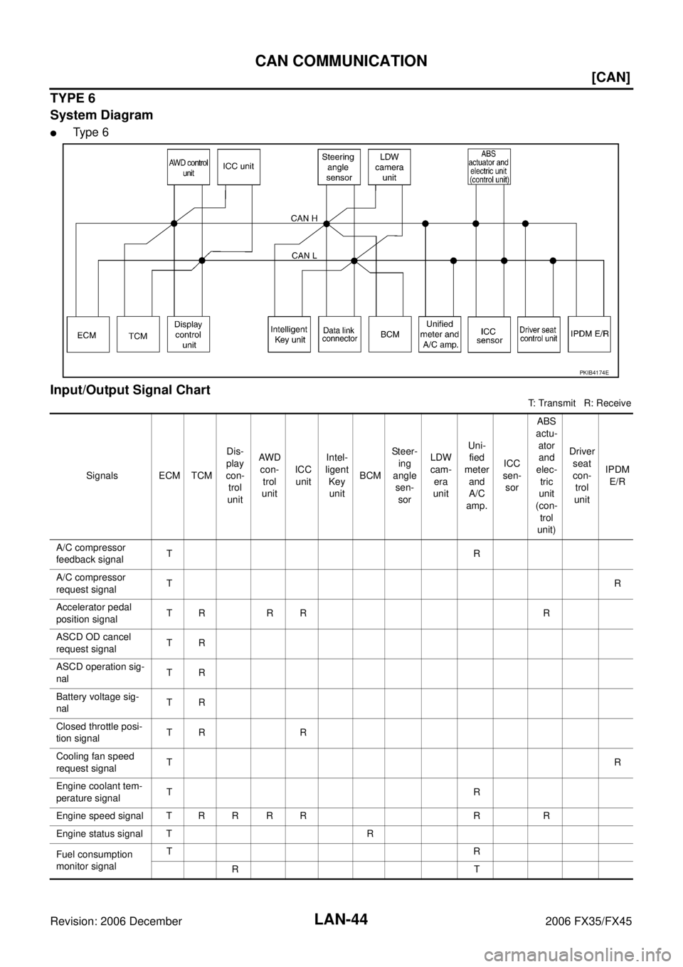
TYPE 6
System Diagram
�Ty p e 6
Input/Output Signal Chart
T: Transmit R: Receive
PKIB4174E
Signals ECM TCM Dis-
play
con- trol
unit AW D
con-
trol
unit ICC
unit Intel-
ligent
Key unit BCM Steer-
ing
angle sen-
sor LDW
cam-
era
unit Uni-
fied
meter
and
A/C
amp. ICC
sen- sor ABS
actu-
ator and
elec-
tric
unit
(con-
trol
unit) Driver
seat
con- trol
unit IPDM
E/R
A/C compressor
feedback signal TR
A/C compressor
request signal T
R
Accelerator pedal
position signal TR R R R
ASCD OD cancel
request signal TR
ASCD operation sig-
nal TR
Battery voltage sig-
nal TR
Closed throttle posi-
tion signal TR R
Cooling fan speed
request signal T
R
Engine coolant tem-
perature signal TR
Engine speed signal T R R R R R R
Engine status signal T R
Fuel consumption
monitor signal TR
RT
Page 3596 of 4462
LT-34
HEADLAMP - XENON TYPE -
Revision: 2006 December 2006 FX35/FX45
Aiming AdjustmentNKS002VS
PREPARATION BEFORE ADJUSTING
For details, refer to the regulations in your own country.
Before performing aiming adjustment, check the following.
1. Keep all tires inflated to correct pressures.
2. Place vehicle on level ground.
3. Set that there is no-load in vehicle other than the driver (or equivalent weight placed in driver's position). Coolant, engine oil filled up to correct level and full fuel tank.
LOW BEAM AND HIGH BEAM
1. Turn headlamp low beam ON.
CAUTION:
Be sure aiming switch is set to “0” when performing aiming
adjustment.
2. Use adjusting screws to perform aiming adjustment.
PKIC9684E
PKIB3650E
Page 3650 of 4462
LT-88
FRONT FOG LAMP
Revision: 2006 December 2006 FX35/FX45
Aiming AdjustmentNKS002X9
Front fog lamp is a semi-sealed beam type which uses a replaceable halogen bulb. Before performing aiming
adjustment, make sure of the following.
�Keep all tires inflated to correct pressure.
�Place vehicle on level ground.
�See that vehicle is unloaded (except for full levels of coolant, engine oil and fuel, and spare tire, jack, and
tools). Have the driver or equivalent weight placed in driver seat.
Adjust aiming in the vertical direction by turning adjusting screw.
1. Set the distance between the screen and the center of front fog lamp lens as shown at left.
2. Turn front fog lamps ON.
3. Adjust front fog lamps using adjusting screw so that the top edge of the high intensity zone is 100 mm (3.94 in) below the height of
front fog lamp centers as shown at left.
�When performing adjustment, if necessary, cover headlamps
and opposite front fog lamp.
PKIC9713E
PKIB1672E
PKIB1673E
Page 3769 of 4462
![INFINITI FX35 2006 Service Manual PRECAUTIONS LU-3
[VQ35DE]
C
D E
F
G H
I
J
K L
M A
LU
Revision: 2006 December 2006 FX35/FX45
[VQ35DE]PRECAUTIONSPFP:00001
Precautions for Liquid GasketNBS003IV
LIQUID GASKET APPLICATION PRO](/manual-img/42/57019/w960_57019-3768.png "INFINITI FX35 2006 Service Manual PRECAUTIONS LU-3
[VQ35DE]
C
D E
F
G H
I
J
K L
M A
LU
Revision: 2006 December 2006 FX35/FX45
[VQ35DE]PRECAUTIONSPFP:00001
Precautions for Liquid GasketNBS003IV
LIQUID GASKET APPLICATION PRO")
PRECAUTIONS LU-3
[VQ35DE]
C
D E
F
G H
I
J
K L
M A
LU
Revision: 2006 December 2006 FX35/FX45
[VQ35DE]PRECAUTIONSPFP:00001
Precautions for Liquid GasketNBS003IV
LIQUID GASKET APPLICATION PROCEDURE
1. Remove old liquid gasket adhering to the liquid gasket application surface and the mating surface.
�Remove liquid gasket completely from the liquid gasket application surface, mounting bolts, and bolt
holes.
2. Wipe the liquid gasket application surface and the mating surface with white gasoline (lighting and heating use) to remove adhering moisture, grease and foreign materials.
3. Apply liquid gasket to the liquid gasket application surface. Use Genuine RTV Silicone Sealant or equivalent. Refer to GI-48, "
RECOMMENDED CHEMICAL
PRODUCTS AND SEALANTS" .
�Within five minutes of liquid gasket application, install the mating component.
�If liquid gasket protrudes, wipe it off immediately.
�Do not retighten after mounting bolts and nuts the installation.
�After 30 minutes or more have passed from the installation, fill engine oil and engine coolant.
Page 3773 of 4462
![INFINITI FX35 2006 Service Manual ENGINE OIL LU-7
[VQ35DE]
C
D E
F
G H
I
J
K L
M A
LU
Revision: 2006 December 2006 FX35/FX45
ENGINE OILPFP:KLA92
InspectionNBS003J0
ENGINE OIL LEVEL
NOTE:
Before starting engine, put vehicl](/manual-img/42/57019/w960_57019-3772.png "INFINITI FX35 2006 Service Manual ENGINE OIL LU-7
[VQ35DE]
C
D E
F
G H
I
J
K L
M A
LU
Revision: 2006 December 2006 FX35/FX45
ENGINE OILPFP:KLA92
InspectionNBS003J0
ENGINE OIL LEVEL
NOTE:
Before starting engine, put vehicl")
ENGINE OIL LU-7
[VQ35DE]
C
D E
F
G H
I
J
K L
M A
LU
Revision: 2006 December 2006 FX35/FX45
ENGINE OILPFP:KLA92
InspectionNBS003J0
ENGINE OIL LEVEL
NOTE:
Before starting engine, put vehicle horizontally and check the engine oil level. If engine is already started, stop
it and allow 10 minutes before checking.
1. Pull out oil level gauge and wipe it clean.
2. Insert oil level gauge and make sure the engine oil level is within the range shown in the figure.
3. If it is out of range, adjust it.
NOTE:
When checking the engine oil level, insert oil level gauge with its
tip aligned with oil level gauge guide on cylinder head. (In figure,
air cleaner case and air duct are removed.)
ENGINE OIL APPEARANCE
�Check engine oil for white turbidity or heavy contamination.
�If engine oil becomes turbid and white, it is highly probable that it is contaminated with engine coolant.
Repair or replace damaged parts.
ENGINE OIL LEAKAGE
Check for engine oil leakage around the following areas:
�Oil pans (lower and upper)
�Oil pan drain plug
�Oil pressure switch
�Oil filter
�Oil filter bracket (AWD models)
�Oil cooler
�Water pump cover
�Chain tensioner cover
�Intake valve timing control cover and intake valve timing control solenoid valve
�Mating surface between cylinder head and rocker cover
�Mating surface between front timing chain case and rear timing chain case
�Mating surface between rear timing chain case and cylinder head
�Mating surface between rear timing chain case and cylinder block.
�Mating surface between rear timing chain case and oil pan (upper)
�Mating surface between cylinder block and cylinder head
PBIC3101E
KBIA1343E
Page 3781 of 4462
![INFINITI FX35 2006 Service Manual OIL COOLER LU-15
[VQ35DE]
C
D E
F
G H
I
J
K L
M A
LU
Revision: 2006 December 2006 FX35/FX45
AWD models
Removal and InstallationNBS003J6
REMOVAL
WARNING:
Be careful not to get burn yoursel](/manual-img/42/57019/w960_57019-3780.png "INFINITI FX35 2006 Service Manual OIL COOLER LU-15
[VQ35DE]
C
D E
F
G H
I
J
K L
M A
LU
Revision: 2006 December 2006 FX35/FX45
AWD models
Removal and InstallationNBS003J6
REMOVAL
WARNING:
Be careful not to get burn yoursel")
OIL COOLER LU-15
[VQ35DE]
C
D E
F
G H
I
J
K L
M A
LU
Revision: 2006 December 2006 FX35/FX45
AWD models
Removal and InstallationNBS003J6
REMOVAL
WARNING:
Be careful not to get burn yourself, as engine oil and engine coolant may be hot.
NOTE:
When removing oil cooler only, step 2 is unnecessary.
1. Remove front engine undercover with power tool.
2. Drain engine coolant from radiator and cylinder block. Refer to CO-11, "
Changing Engine Coolant" and
EM-124, "
DISASSEMBLY" .
NOTE:
Perform this step when removing water pipes.
3. Disconnect water hoses from oil cooler.
�When removing oil cooler only, pinching water hoses near oil cooler to prevent engine coolant from
spilling out.
�Remaining engine coolant in piping will come out. Use a tray to collect it.
CAUTION:
�Perform this step when the engine is cold.
�Do not spill engine coolant on drive belts.
4. Using oil filter wrench [SST: KV10115801 (J38956)], remove oil filter. Refer to LU-10, "
OIL FILTER" .
CAUTION:
Do not spill engine oil on drive belts.
5. Remove connector bolt, and remove oil cooler.
SBIA0584E
1. Oil filter 2. Connector bolt 3. Oil cooler
4. O-ring 5. Relief valve 6. Oil filter bracket
7. Water hose 8. Water hose 9. Water pipe
10. Water hose