Page 819 of 4462

PRECAUTIONS BL-5
C
D E
F
G H
J
K L
M A
B
BL
Revision: 2006 December 2006 FX35/FX45
PRECAUTIONSPFP:00001
Precautions for Supplemental Restraint System (SRS) “AIR BAG” and “SEAT
BELT PRE-TENSIONER”
NIS001LF
The Supplemental Restraint System such as “AIR BAG” and “SEAT BELT PRE-TENSIONER”, used along
with a front seat belt, helps to reduce the risk or severity of injury to the driver and front passenger for certain
types of collision. This system includes seat belt switch inputs and dual stage front air bag modules. The SRS
system uses the seat belt switches to determine the front air bag deployment, and may only deploy one front
air bag, depending on the severity of a collision and whether the front occupants are belted or unbelted.
Information necessary to service the system safely is included in the SRS and SB section of this Service Man-
ual.
WARNING:
�To avoid rendering the SRS inoperative, which could increase the risk of personal injury or death
in the event of a collision which would result in air bag inflation, all maintenance must be per-
formed by an authorized NISSAN/INFINITI dealer.
�Improper maintenance, including incorrect removal and installation of the SRS, can lead to per-
sonal injury caused by unintentional activation of the system. For removal of Spiral Cable and Air
Bag Module, see the SRS section.
�Do not use electrical test equipment on any circuit related to the SRS unless instructed to in this
Service Manual. SRS wiring harnesses can be identified by yellow and/or orange harnesses or
harness connectors.
Precautions Necessary for Steering Wheel Rotation After Battery DisconnectNIS001LG
NOTE:
�This Procedure is applied only to models with Intelligent Key system and NVIS/IVIS (NISSAN/INFINITI
VEHICLE IMMOBILIZER SYSTEM - NATS).
�Remove and install all control units after disconnecting both battery cables with the ignition knob in the
″ LOCK ″ position.
�Always use CONSULT-II to perform self-diagnosis as a part of each function inspection after finishing
work. If DTC is detected, perform trouble diagnosis according to self-diagnostic results.
For models equipped with the Intelligent Key system and NVIS/IVIS, an electrically controlled steering lock
mechanism is adopted on the key cylinder.
For this reason, if the battery is disconnected or if the battery is discharged, the steering wheel will lock and
steering wheel rotation will become impossible.
If steering wheel rotation is required when battery power is interrupted, follow the procedure below before
starting the repair operation.
OPERATION PROCEDURE
1. Connect both battery cables.
NOTE:
Supply power using jumper cables if battery is discharged.
2. Use the Intelligent Key or mechanical key to turn the ignition switch to the ″ACC ″ position. At this time, the
steering lock will be released.
3. Disconnect both battery cables. The steering lock will remain released and the steering wheel can be rotated.
4. Perform the necessary repair operation.
5. When the repair work is completed, return the ignition switch to the ″LOCK ″ position before connecting
the battery cables. (At this time, the steering lock mechanism will engage.)
6. Perform a self-diagnosis check of all control units using CONSULT-II.
Precautions for WorkNIS001LH
�After removing and installing the opening/closing parts, be sure to carry out fitting adjustments to check
their operation.
�Check the lubrication level, damage, and wear of each part. If necessary, grease or replace it.
Page 836 of 4462

BL-22
POWER DOOR LOCK SYSTEM
Revision: 2006 December 2006 FX35/FX45
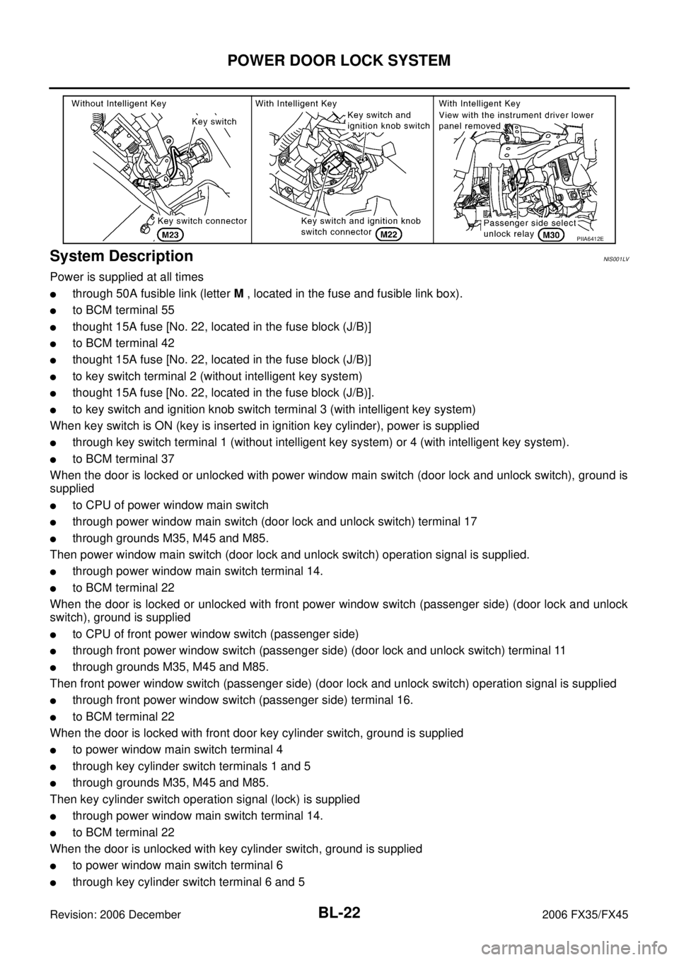
System DescriptionNIS001LV
Power is supplied at all times
�through 50A fusible link (letter M , located in the fuse and fusible link box).
�to BCM terminal 55
�thought 15A fuse [No. 22, located in the fuse block (J/B)]
�to BCM terminal 42
�thought 15A fuse [No. 22, located in the fuse block (J/B)]
�to key switch terminal 2 (without intelligent key system)
�thought 15A fuse [No. 22, located in the fuse block (J/B)].
�to key switch and ignition knob switch terminal 3 (with intelligent key system)
When key switch is ON (key is inserted in ignition key cylinder), power is supplied
�through key switch terminal 1 (without intelligent key system) or 4 (with intelligent key system).
�to BCM terminal 37
When the door is locked or unlocked with power window main switch (door lock and unlock switch), ground is
supplied
�to CPU of power window main switch
�through power window main switch (door lock and unlock switch) terminal 17
�through grounds M35, M45 and M85.
Then power window main switch (door lock and unlock switch) operation signal is supplied.
�through power window main switch terminal 14.
�to BCM terminal 22
When the door is locked or unlocked with front power window switch (passenger side) (door lock and unlock
switch), ground is supplied
�to CPU of front power window switch (passenger side)
�through front power window switch (passenger side) (door lock and unlock switch) terminal 11
�through grounds M35, M45 and M85.
Then front power window switch (passenger side) (door lock and unlock switch) operation signal is supplied
�through front power window switch (passenger side) terminal 16.
�to BCM terminal 22
When the door is locked with front door key cylinder switch, ground is supplied
�to power window main switch terminal 4
�through key cylinder switch terminals 1 and 5
�through grounds M35, M45 and M85.
Then key cylinder switch operation signal (lock) is supplied
�through power window main switch terminal 14.
�to BCM terminal 22
When the door is unlocked with key cylinder switch, ground is supplied
�to power window main switch terminal 6
�through key cylinder switch terminal 6 and 5
PIIA6412E
Page 839 of 4462
POWER DOOR LOCK SYSTEM BL-25
C
D E
F
G H
J
K L
M A
B
BL
Revision: 2006 December 2006 FX35/FX45
Schematic/With Intelligent KeyNIS001LY
TIWM1714E
Page 840 of 4462
BL-26
POWER DOOR LOCK SYSTEM
Revision: 2006 December 2006 FX35/FX45
Wiring Diagram — D/LOCK —/With Intelligent KeyNIS001LZ
TIWM1649E
Page 845 of 4462
POWER DOOR LOCK SYSTEM BL-31
C
D E
F
G H
J
K L
M A
B
BL
Revision: 2006 December 2006 FX35/FX45
Schematic/Without Intelligent KeyNIS001M0
TIWM0321E
Page 846 of 4462
BL-32
POWER DOOR LOCK SYSTEM
Revision: 2006 December 2006 FX35/FX45
Wiring Diagram — D/LOCK —/Without Intelligent KeyNIS001M1
TIWM1653E
Page 850 of 4462

BL-36
POWER DOOR LOCK SYSTEM
Revision: 2006 December 2006 FX35/FX45
Terminals and Reference Value for BCMNIS001M2
Terminals and Reference Value for Intelligent Key Unit (With Intelligent Key Sys-
tem)
NIS001M3
Te r m i -
nal Wire
Color Item Signal
Input/
output Condition
Voltage (V)
Approx.
12 P/B Front door switch (Pas-
senger side) Input ON (door open)
→ OFF (door closed) 0 → Battery voltage
13 P/L Rear door switch RH Input ON (door open) → OFF (door closed) 0 → Battery voltage
22 OR Power window serial link Input/
Output Ignition switch ON
37 B/W Key switch Input ON (Key inserted)
→ OFF (Key
removed from IGN key cylinder) Battery voltage
→ 0
39 L CAN H Input/
Output ——
40 P CAN L Input/
Output ——
42 L/R Battery power supply
(fuse) Input — Battery voltage
44 Y Driver door lock actuator
(unlock) Output Door lock / unlock switch
(Free → Unlock) 0
→ Battery voltage → 0
49 B Ground — — 0
50 PU Door lock actuator (lock) Output Door lock / unlock switch
(Free → Lock) 0
→ Battery voltage → 0
51 W/B Passenger and rear doors
lock actuator (unlock) Output
Door lock / unlock switch
(Free → Unlock) 0
→ Battery voltage → 0
52 B Ground — — 0
55 G Power source (Fusible
link) Input — Battery voltage
58 L Back door switch Input ON (Door open) → OFF (Door closed) 0 → 9
62 W Front door switch (Driver
side) Input ON (Door open)
→ OFF (Door closed) 0 → Battery voltage
63 P Rear door switch LH Input ON (Door open) → OFF (Door closed) 0 → Battery voltage
PIIA2344J
Te r m i -
nal Wire
Color Item Signal
Input/
output Condition
Voltage (V)
Approx.
2 L CAN H Input/
Output ——
3 P CAN L Input/
Output ——
27 L/W Push switch Input Push switch (OFF → ON) 0 → Battery voltage
40 BR/W AS unlock output signal Output Door lock / unlock switch
(Free → Unlock) 0
→ Battery voltage
Page 851 of 4462

POWER DOOR LOCK SYSTEM BL-37
C
D E
F
G H
J
K L
M A
B
BL
Revision: 2006 December 2006 FX35/FX45
Work FlowNIS001M4
1. Check the symptom and customer's requests.
2. Understand the outline of system. Refer to BL-22, "
System Description" .
3. According to the trouble diagnosis chart by symptom, repair or replace the cause of the malfunction. Refer to BL-38, "
Trouble Diagnosis Chart by Symptom" .
4. Does power door lock system operate normally? YES: GO TO 5.
NO: GO TO 3.
5. INSPECTION END
CONSULT-II Function (BCM)NIS001M5
CONSULT-II can display each diagnostic item using the diagnostic test modes shown.
CONSULT-II START PROCEDURE
Refer to GI-38, "CONSULT-II Start Procedure" .
CONSULT-II APPLICATION ITEMS
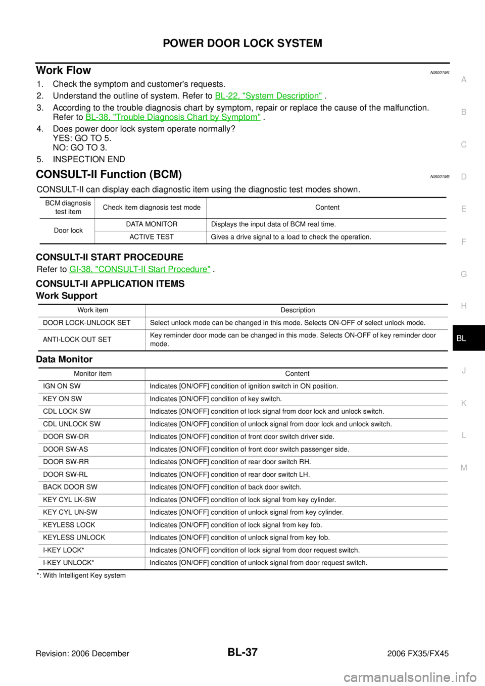
Work Support
Data Monitor
*: With Intelligent Key system BCM diagnosis
test item Check item diagnosis test mode Content
Door lock DATA MONITOR Displays the input data of BCM real time.
ACTIVE TEST Gives a drive signal to a load to check the operation.
Work item Description
DOOR LOCK-UNLOCK SET Select unlock mode can be changed in this mode. Selects ON-OFF of select unlock mode.
ANTI-LOCK OUT SET Key reminder door mode can be changed in this mode. Selects ON-OFF of key reminder door
mode.
Monitor item Content
IGN ON SW Indicates [ON/OFF] condition of ignition switch in ON position.
KEY ON SW Indicates [ON/OFF] condition of key switch.
CDL LOCK SW Indicates [ON/OFF] condition of lock signal from door lock and unlock switch.
CDL UNLOCK SW Indicates [ON/OFF] condition of unlock signal from door lock and unlock switch.
DOOR SW-DR Indicates [ON/OFF] condition of front door switch driver side.
DOOR SW-AS Indicates [ON/OFF] condition of front door switch passenger side.
DOOR SW-RR Indicates [ON/OFF] condition of rear door switch RH.
DOOR SW-RL Indicates [ON/OFF] condition of rear door switch LH.
BACK DOOR SW Indicates [ON/OFF] condition of back door switch.
KEY CYL LK-SW Indicates [ON/OFF] condition of lock signal from key cylinder.
KEY CYL UN-SW Indicates [ON/OFF] condition of unlock signal from key cylinder.
KEYLESS LOCK Indicates [ON/OFF] condition of lock signal from key fob.
KEYLESS UNLOCK Indicates [ON/OFF] condition of unlock signal from key fob.
I-KEY LOCK* Indicates [ON/OFF] condition of lock signal from door request switch.
I-KEY UNLOCK* Indicates [ON/OFF] condition of unlock signal from door request switch.