Page 1194 of 4462
BRC-62
[VDC/TCS/ABS]
STEERING ANGLE SENSOR
Revision: 2006 December 2006 FX35/FX45
Page 1222 of 4462
![INFINITI FX35 2006 Service Manual CO-28
[VQ35DE]
WATER INLET AND THERMOSTAT ASSEMBLY
Revision: 2006 December 2006 FX35/FX45
INSPECTION AFTER REMOVAL
1. Check valve seating condition at ordinary room temperatures. It should seat tightl INFINITI FX35 2006 Service Manual CO-28
[VQ35DE]
WATER INLET AND THERMOSTAT ASSEMBLY
Revision: 2006 December 2006 FX35/FX45
INSPECTION AFTER REMOVAL
1. Check valve seating condition at ordinary room temperatures. It should seat tightl](/manual-img/42/57019/w960_57019-1221.png)
CO-28
[VQ35DE]
WATER INLET AND THERMOSTAT ASSEMBLY
Revision: 2006 December 2006 FX35/FX45
INSPECTION AFTER REMOVAL
1. Check valve seating condition at ordinary room temperatures. It should seat tightly.
2. Check valve operation.
�If the malfunctioning condition, when valve seating at ordinary
room temperature, or measured values are out of the standard,
replace water inlet and thermostat assembly.
INSTALLATION
Note the following, and install in the reverse order of removal.
�Be careful not to spill engine coolant over engine room. Use rag to absorb engine coolant.
INSPECTION AFTER INSTALLATION
�Check for leaks of engine coolant using the radiator cap tester adapter [SST: EG17650301 (J33984-A)]
and the radiator cap tester (commercial service tool). Refer to CO-11, "
LEAK CHECK" .
�Start and warm up the engine. Visually make sure that there is no leaks of engine coolant.
Thermostat
Valve opening temperature 76 - 79 °C (169 - 174 °F)
Maximum valve lift 8.6 mm / 90 °C (0.339 in / 194 °F)
Valve closing temperature 71 °C (160 °F)
SLC949A
Page 1248 of 4462
![INFINITI FX35 2006 Service Manual CO-54
[VK45DE]
THERMOSTAT AND WATER CONTROL VALVE
Revision: 2006 December 2006 FX35/FX45
�Refer to GI-11, "Components" for symbol marks in the figure.
Removal and InstallationNBS003KS
REMOVAL
1. Dra INFINITI FX35 2006 Service Manual CO-54
[VK45DE]
THERMOSTAT AND WATER CONTROL VALVE
Revision: 2006 December 2006 FX35/FX45
�Refer to GI-11, "Components" for symbol marks in the figure.
Removal and InstallationNBS003KS
REMOVAL
1. Dra](/manual-img/42/57019/w960_57019-1247.png)
CO-54
[VK45DE]
THERMOSTAT AND WATER CONTROL VALVE
Revision: 2006 December 2006 FX35/FX45
�Refer to GI-11, "Components" for symbol marks in the figure.
Removal and InstallationNBS003KS
REMOVAL
1. Drain engine coolant from drain plugs on radiator and both side of cylinder block. Refer to CO-38, "Chang-
ing Engine Coolant" and EM-249, "DISASSEMBLY" .
CAUTION:
�Perform this step when engine is cold.
�Do not spill engine coolant on drive belts.
2. Remove engine cover with power tool. Refer to EM-173, "
ENGINE ROOM COVER" .
3. Remove air duct (inlet). Refer to EM-177, "
AIR CLEANER AND AIR DUCT" .
4. Disconnect water suction hose from water inlet.
5. Remove water inlet and thermostat. CAUTION:
Do not disassemble thermostat.
6. Remove intake manifolds (upper and lower). Refer to EM-179, "
INTAKE MANIFOLD" .
7. Disconnect radiator hose (upper) and water hoses from thermostat housing.
8. Disconnect heater hoses from water outlet and heater pipe.
9. Remove thermostat housing, water outlet pipe, water connector, water control valve, water outlet and heater pipe.
CAUTION:
Do not disassemble water control valve.
INSPECTION AFTER REMOVAL
�Make sure that valves both in thermostat and water control valve are completely closing at normal temper-
ature.
�Place a thread so that it is caught in the valves of the thermostat
and water control valve. Immerse fully in a container filled with
water. Heat while stirring. (The example in the figure shows ther-
mostat.)
�The valve opening temperature is the temperature at which the
valve opens and falls from the thread.
�Continue heating. Check the maximum valve lift.
NOTE:
The maximum valve lift standard temperature for water control
valve is the reference value.
� After checking the maximum valve lift, lower the water tempera-
ture and check the valve closing temperature.
Standard values:
�If the malfunctioning condition, when closing valve at normal temperature, or measured values are out of
the standard, replace thermostat and/or water control valve.
INSTALLATION
Note the following, and install in the reverse order of removal.
CAUTION:
Be careful not to spill engine coolant over engine room. Use rag to absorb engine coolant.
D. To heater core E. To cylinder head (left bank) F. To cylinder head (right bank)
G. To intake manifold adapter
SLC252B
Thermostat Water control valve
Valve opening temperature 80 - 84 °C (176 - 183 °F) 93.5 - 96.5 °C (200 - 206 °F)
Maximum valve lift More than 10 mm/ 95
°C
(0.39 in/ 203 °F) More than 8 mm/ 108
°C
(0.315 in/ 226 °F)
Valve closing temperature 77 °C (171 °F) 90 °C (194 °F)
Page 1256 of 4462

DI-6
COMBINATION METERS
Revision: 2006 December 2006 FX35/FX45
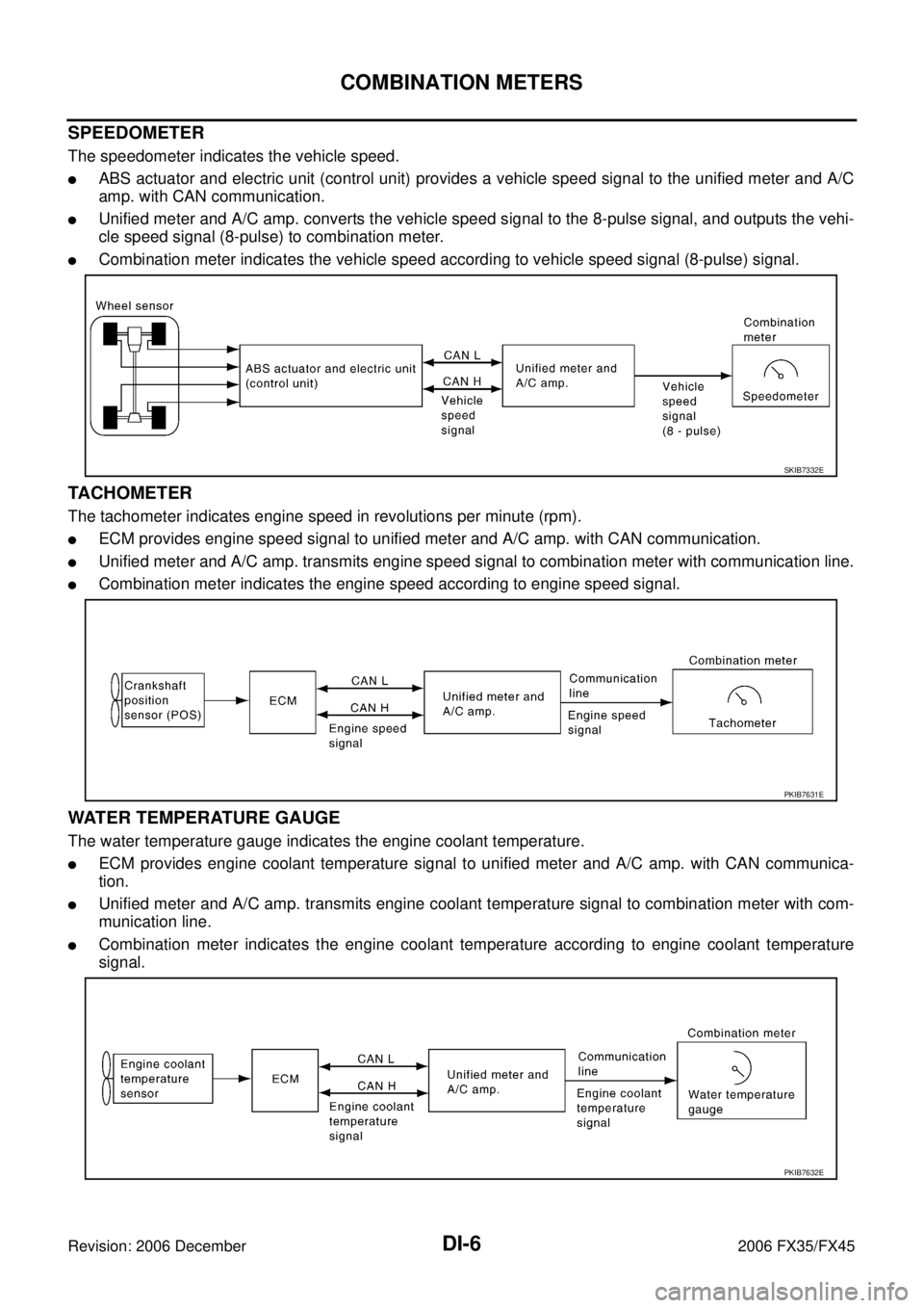
SPEEDOMETER
The speedometer indicates the vehicle speed.
�ABS actuator and electric unit (control unit) provides a vehicle speed signal to the unified meter and A/C
amp. with CAN communication.
�Unified meter and A/C amp. converts the vehicle speed signal to the 8-pulse signal, and outputs the vehi-
cle speed signal (8-pulse) to combination meter.
�Combination meter indicates the vehicle speed according to vehicle speed signal (8-pulse) signal.
TACHOMETER
The tachometer indicates engine speed in revolutions per minute (rpm).
�ECM provides engine speed signal to unified meter and A/C amp. with CAN communication.
�Unified meter and A/C amp. transmits engine speed signal to combination meter with communication line.
�Combination meter indicates the engine speed according to engine speed signal.
WATER TEMPERATURE GAUGE
The water temperature gauge indicates the engine coolant temperature.
�ECM provides engine coolant temperature signal to unified meter and A/C amp. with CAN communica-
tion.
�Unified meter and A/C amp. transmits engine coolant temperature signal to combination meter with com-
munication line.
�Combination meter indicates the engine coolant temperature according to engine coolant temperature
signal.
SKIB7332E
PKIB7631E
PKIB7632E
Page 1257 of 4462

COMBINATION METERS DI-7
C
D E
F
G H
I
J
L
M A
B
DI
Revision: 2006 December 2006 FX35/FX45
FUEL GAUGE
The fuel gauge indicates the approximate fuel level in the fuel tank.
�Unified meter and A/C amp. reads a resistor signal from fuel level sensor.
Signal is supplied
–from unified meter and A/C amp. terminal 36
–through the fuel level sensor unit and fuel pump (main) terminals 5 and 2, and
–through the fuel level sensor unit (sub) terminals 2 and 1
–to unified meter and A/C amp. terminal 28 for the fuel gauge.
�Unified meter and A/C amp. provides a fuel level signal to combination meter with communication line.
�Combination meter indicates the approximate fuel level according to the fuel level signal.
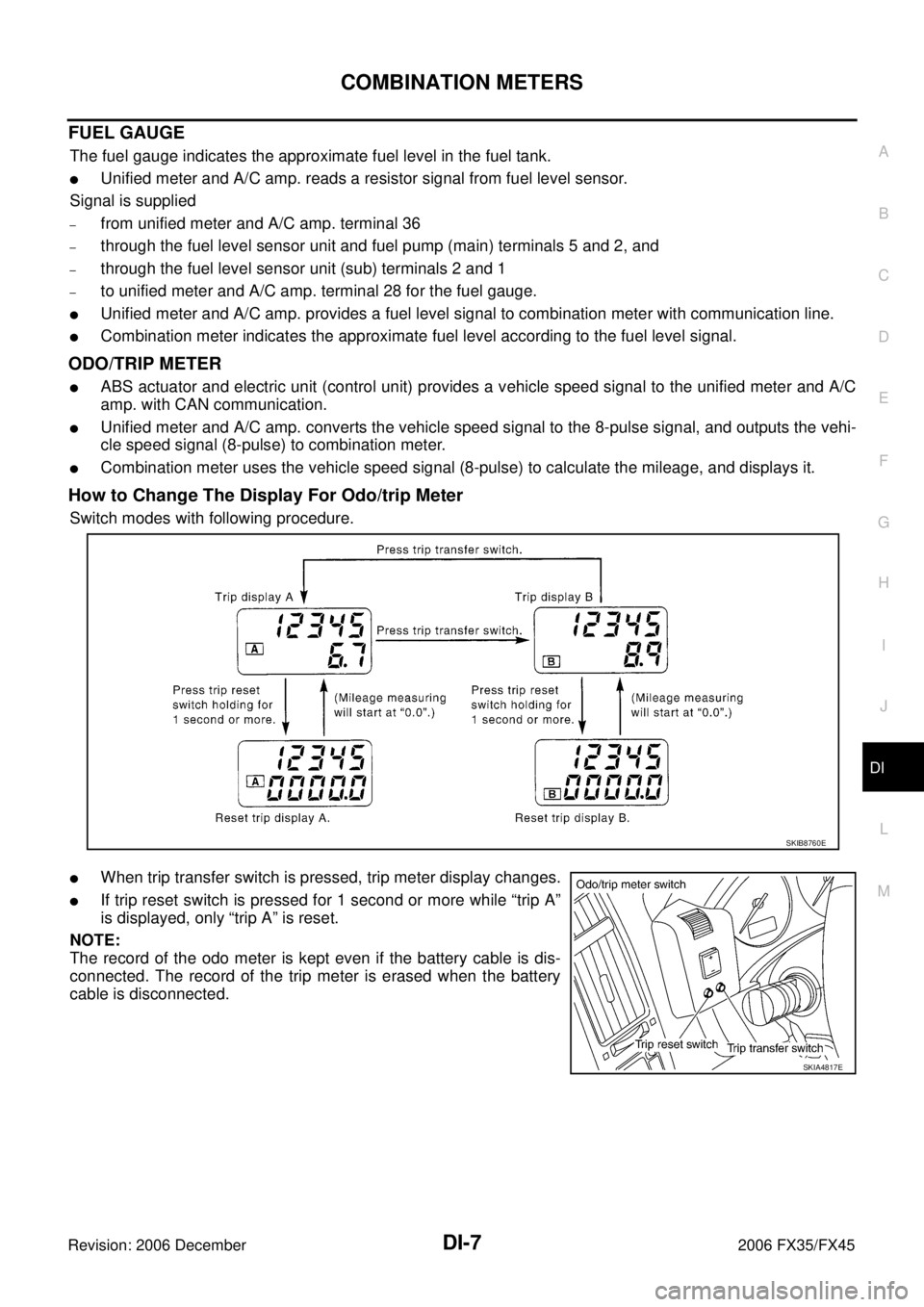
ODO/TRIP METER
�ABS actuator and electric unit (control unit) provides a vehicle speed signal to the unified meter and A/C
amp. with CAN communication.
�Unified meter and A/C amp. converts the vehicle speed signal to the 8-pulse signal, and outputs the vehi-
cle speed signal (8-pulse) to combination meter.
�Combination meter uses the vehicle speed signal (8-pulse) to calculate the mileage, and displays it.
How to Change The Display For Odo/trip Meter
Switch modes with following procedure.
�When trip transfer switch is pressed, trip meter display changes.
�If trip reset switch is pressed for 1 second or more while “trip A”
is displayed, only “trip A” is reset.
NOTE:
The record of the odo meter is kept even if the battery cable is dis-
connected. The record of the trip meter is erased when the battery
cable is disconnected.
SKIB8760E
SKIA4817E
Page 1258 of 4462

DI-8
COMBINATION METERS
Revision: 2006 December 2006 FX35/FX45
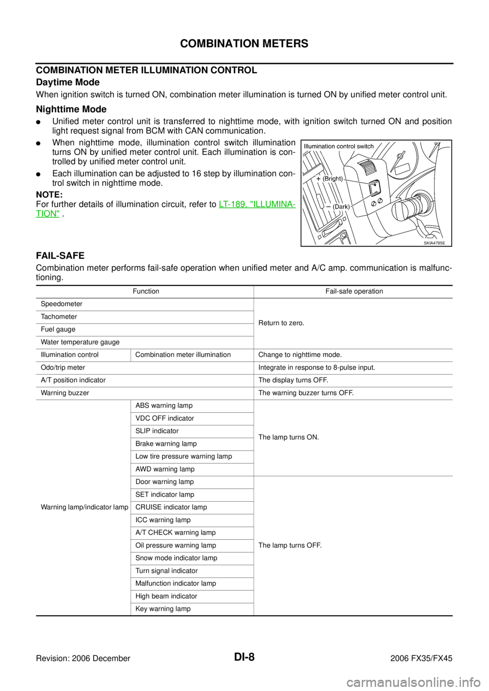
COMBINATION METER ILLUMINATION CONTROL
Daytime Mode
When ignition switch is turned ON, combination meter illumination is turned ON by unified meter control unit.
Nighttime Mode
�Unified meter control unit is transferred to nighttime mode, with ignition switch turned ON and position
light request signal from BCM with CAN communication.
�When nighttime mode, illumination control switch illumination
turns ON by unified meter control unit. Each illumination is con-
trolled by unified meter control unit.
�Each illumination can be adjusted to 16 step by illumination con-
trol switch in nighttime mode.
NOTE:
For further details of illumination circuit, refer to LT- 1 8 9 , "
ILLUMINA-
TION" .
FAIL-SAF E
Combination meter performs fail-safe operation when unified meter and A/C amp. communication is malfunc-
tioning.
SKIA4795E
Function Fail-safe operation
Speedometer
Return to zero.
Tachometer
Fuel gauge
Water temperature gauge
Illumination control Combination meter illumination Change to nighttime mode.
Odo/trip meter Integrate in response to 8-pulse input.
A/T position indicator The display turns OFF.
Warning buzzer The warning buzzer turns OFF.
Warning lamp/indicator lamp ABS warning lamp
The lamp turns ON.
VDC OFF indicator
SLIP indicator
Brake warning lamp
Low tire pressure warning lamp
AWD warning lamp
Door warning lamp
The lamp turns OFF.
SET indicator lamp
CRUISE indicator lamp
ICC warning lamp
A/T CHECK warning lamp
Oil pressure warning lamp
Snow mode indicator lamp
Turn signal indicator
Malfunction indicator lamp
High beam indicator
Key warning lamp
Page 1269 of 4462

COMBINATION METERS DI-19
C
D E
F
G H
I
J
L
M A
B
DI
Revision: 2006 December 2006 FX35/FX45
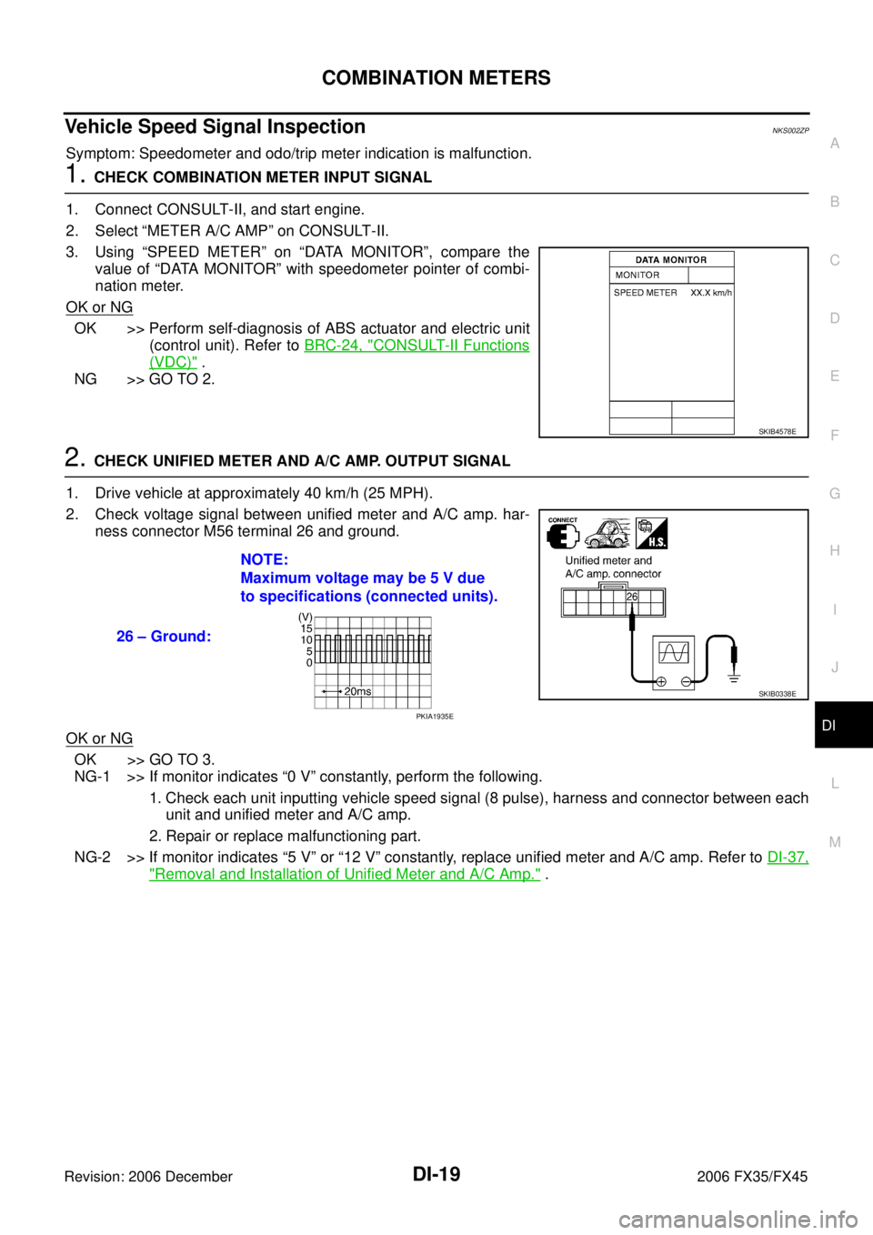
Vehicle Speed Signal InspectionNKS002ZP
Symptom: Speedometer and odo/trip meter indication is malfunction.
1. CHECK COMBINATION METER INPUT SIGNAL
1. Connect CONSULT-II, and start engine.
2. Select “METER A/C AMP” on CONSULT-II.
3. Using “SPEED METER” on “DATA MONITOR”, compare the value of “DATA MONITOR” with speedometer pointer of combi-
nation meter.
OK or NG
OK >> Perform self-diagnosis of ABS actuator and electric unit (control unit). Refer to BRC-24, "
CONSULT-II Functions
(VDC)" .
NG >> GO TO 2.
2. CHECK UNIFIED METER AND A/C AMP. OUTPUT SIGNAL
1. Drive vehicle at approximately 40 km/h (25 MPH).
2. Check voltage signal between unified meter and A/C amp. har- ness connector M56 terminal 26 and ground.
OK or NG
OK >> GO TO 3.
NG-1 >> If monitor indicates “0 V” constantly, perform the following.
1. Check each unit inputting vehicle speed signal (8 pulse), harness and connector between each unit and unified meter and A/C amp.
2. Repair or replace malfunctioning part.
NG-2 >> If monitor indicates “5 V” or “12 V” constantly, replace unified meter and A/C amp. Refer to DI-37,
"Removal and Installation of Unified Meter and A/C Amp." .
SKIB4578E
26 – Ground: NOTE:
Maximum voltage may be 5 V due
to specifications (connected units).
SKIB0338E
PKIA1935E
Page 1276 of 4462
DI-26
COMBINATION METERS
Revision: 2006 December 2006 FX35/FX45
DISASSEMBLY
1. Remove screws (A) and remove rear cover (1).
2. Disconnect odo/trip meter and illumination control switch con- nector (2).
3. Remove screws (A).
4. Remove tabs (A) and remove switch and meter housing (1).
5. Remove screws (A) and remove reinforcing metal (1).
SKIB8477E
SKIB8478E
SKIB8479E
SKIB8480E