Page 745 of 4462

NAVIGATION SYSTEM AV-139
C
D E
F
G H
I
J
L
M A
B
AV
Revision: 2006 December 2006 FX35/FX45
Unable to Operate System with A/C and AV SwitchNKS003KN
Symptom: Unable to operate A/C system, audio system and navigation system with A/C and AV switch.
(Unable to start self-diagnosis.)
1. CHECK CONDITION
1. Turn ignition switch ON.
2. Check if an image is displayed on the screen.
Is an image displayed on the screen?
YES >> GO TO 2.
NO >> Repair malfunctioning part. Refer to AV- 1 4 1 , "
All Images Are Not Displayed" .
2. SELF-DIAGNOSIS OF A/C AND AV SWITCH
Start self-diagnosis of A/C and AV switch, and check the self-diagnosis result. Refer to AV- 1 3 7 , "
A/C and AV
Switch Self-Diagnosis Function" .
OK or NG
OK >> GO TO 4.
NG >> GO TO 3.
3. CHECK A/C AND AV SWITCH POWER SUPPLY AND GROUND CIRCUIT
1. Check voltage between A/C and AV switch harness connector terminals and ground.
2. Turn ignition switch OFF.
3. Disconnect A/C and AV switch connector.
4. Check continuity between A/C and AV switch harness connector M64 terminal 5 and ground.
OK or NG
OK >> Replace A/C and AV switch.
NG >> Repair harness or connector.
Te r m i n a l s
OFF ACC ON
(+)
(–)
Connector Terminal
M64 1
Ground Battery
voltage Battery
voltage Battery
voltage
20 V Battery
voltage Battery
voltage
5 – Ground : Continuity should exist.
SKIB7836E
SKIB7837E
Page 746 of 4462
AV-140
NAVIGATION SYSTEM
Revision: 2006 December 2006 FX35/FX45
4. CHECK HARNESS
1. Turn ignition switch OFF.
2. Disconnect display control unit and A/C and AV switch connectors.
3. Check continuity between display control unit harness connector (A) M76 terminals 28, 30 and A/C and AV switch harness con-
nector (B) M64 terminals 6, 8.
4. Check continuity between display control unit harness connector (A) M76 terminals 28, 30 and ground.
OK or NG
OK >> GO TO 5.
NG >> Repair harness or connector.
5. CHECK A/C AND AV SWITCH AND DISPLAY CONTROL UNIT
1. Replace A/C and AV switch or display control unit.
2. Make sure that A/C system, audio system and navigation system can be operated by A/C and AV switch.
OK or NG
OK >> INSPECTION END
NG >> Replace the other unit. 28 – 6 : Continuity should exist.
30 – 8 : Continuity should exist.
28, 30 – Ground : Continuity should not exist.
SKIB7838E
Page 747 of 4462

NAVIGATION SYSTEM AV-141
C
D E
F
G H
I
J
L
M A
B
AV
Revision: 2006 December 2006 FX35/FX45
All Images Are Not DisplayedNKS003KO
Symptom: RGB image is not displayed.
1. CHECK CONDITION
When operating audio and air conditioner, make sure that they operate correctly.
Do audio and air conditioner operate normally?
YES >> GO TO 2.
NO >> GO TO 5.
2. CHECK DISPLAY GROUND CIRCUIT
1. Turn ignition switch OFF.
2. Disconnect display connector.
3. Check continuity between display harness connector M63 termi- nal 1 and ground.
OK or NG
OK >> GO TO 3.
NG >> Repair harness or connector.
3. CHECK HARNESS
1. Disconnect display control unit connector.
2. Check continuity between display control unit harness connector (A) M75 terminals 2, 4, 5, 7 and display harness connector (B)
M63 terminals 2, 3, 13, 14.
3. Check continuity between display control unit harness connector (A) M75 terminals 2, 4 and ground.
OK or NG
OK >> GO TO 4.
NG >> Repair harness or connector. 1 – Ground : Continuity should exist.
SKIB7839E
2 – 2 : Continuity should exist.
4 – 3 : Continuity should exist.
5 – 13 : Continuity should exist.
7 – 14 : Continuity should exist.
2, 4 – Ground : Continuity should not exist.
SKIB7840E
Page 749 of 4462

NAVIGATION SYSTEM AV-143
C
D E
F
G H
I
J
L
M A
B
AV
Revision: 2006 December 2006 FX35/FX45
Status Screen for Audio and A/C Is Not Displayed When Showing Map ScreenNKS003KQ
Symptom: Status screen is not displayed in the lower portion of map screen when operating audio system and
A/C system.
1. CHECK HARNESS
1. Turn ignition switch OFF.
2. Disconnect display control unit and display connectors.
3. Check continuity between display control unit harness connector (A) M76 terminals 53, 55 and display harness connector (B)
M63 terminals 20, 8.
4. Check continuity between display control unit harness connector (A) M76 terminals 53, 55 and ground.
OK or NG
OK >> GO TO 2.
NG >> Repair harness or connector.
2. CHECK VERTICAL SYNCHRONIZING (VP) SIGNAL
1. Connect display control unit and display connectors.
2. Turn ignition switch ON.
3. Check voltage waveform between display control unit harness connector M76 terminal 53 and ground with CONSULT-II or
oscilloscope.
OK or NG
OK >> GO TO 3.
NG >> Replace display.
3. CHECK HORIZONTAL SYNCHRONIZING (HP) SIGNAL
Check voltage waveform between display control unit harness con-
nector M76 terminal 55 and ground with CONSULT-II or oscillo-
scope.
OK or NG
OK >> Replace display control unit.
NG >> Replace display. 53 – 20 : Continuity should exist.
55 – 8 : Continuity should exist.
53, 55 – Ground : Continuity should not exist.
SKIB7850E
53 – Ground:
SKIB7851ESKIB3598E
55 – Ground:
SKIB7852ESKIB3601E
Page 753 of 4462

NAVIGATION SYSTEM AV-147
C
D E
F
G H
I
J
L
M A
B
AV
Revision: 2006 December 2006 FX35/FX45
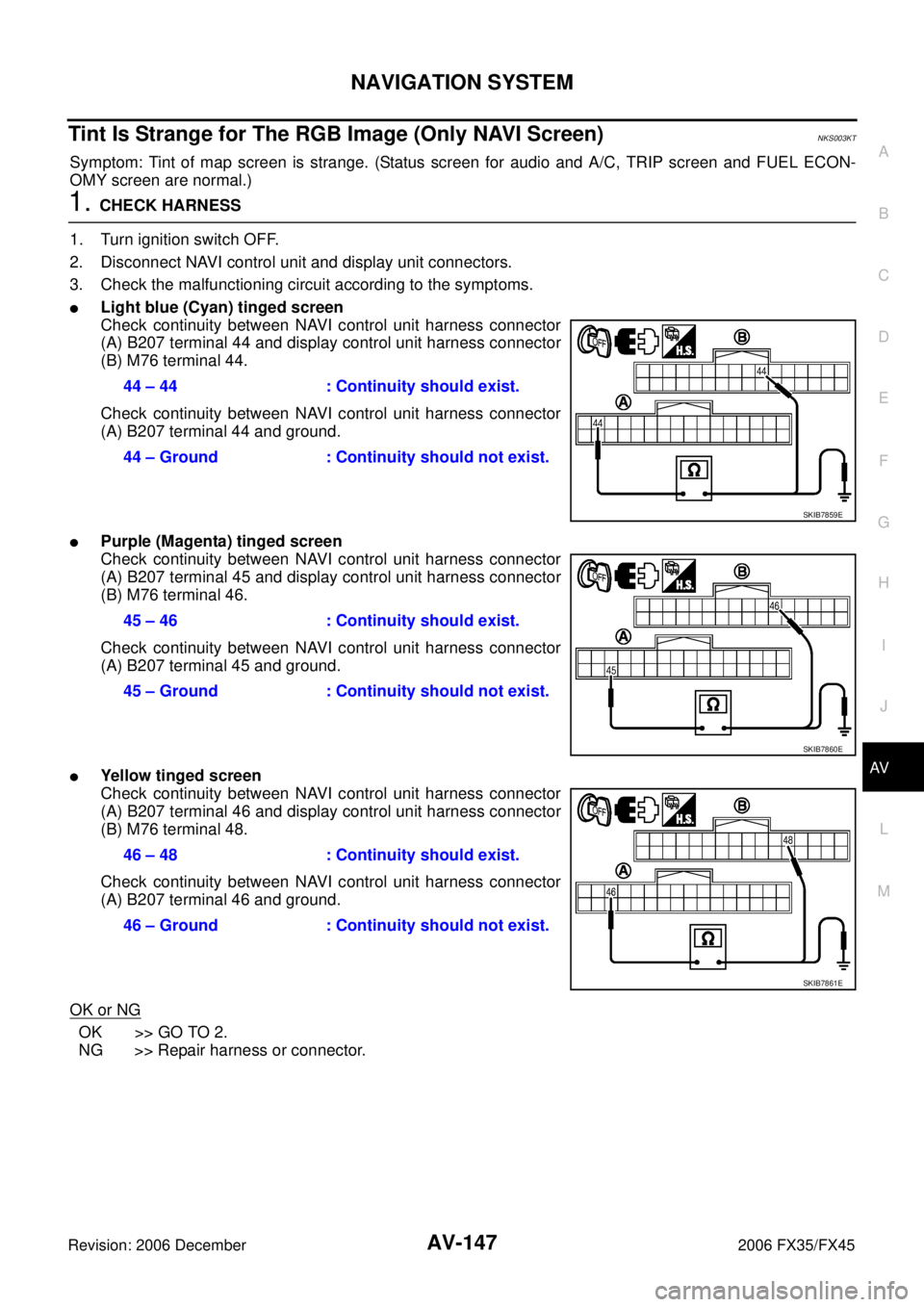
Tint Is Strange for The RGB Image (Only NAVI Screen)NKS003KT
Symptom: Tint of map screen is strange. (Status screen for audio and A/C, TRIP screen and FUEL ECON-
OMY screen are normal.)
1. CHECK HARNESS
1. Turn ignition switch OFF.
2. Disconnect NAVI control unit and display unit connectors.
3. Check the malfunctioning circuit according to the symptoms.
�Light blue (Cyan) tinged screen
Check continuity between NAVI control unit harness connector
(A) B207 terminal 44 and display control unit harness connector
(B) M76 terminal 44.
Check continuity between NAVI control unit harness connector
(A) B207 terminal 44 and ground.
�Purple (Magenta) tinged screen
Check continuity between NAVI control unit harness connector
(A) B207 terminal 45 and display control unit harness connector
(B) M76 terminal 46.
Check continuity between NAVI control unit harness connector
(A) B207 terminal 45 and ground.
�Yellow tinged screen
Check continuity between NAVI control unit harness connector
(A) B207 terminal 46 and display control unit harness connector
(B) M76 terminal 48.
Check continuity between NAVI control unit harness connector
(A) B207 terminal 46 and ground.
OK or NG
OK >> GO TO 2.
NG >> Repair harness or connector. 44 – 44 : Continuity should exist.
44 – Ground : Continuity should not exist.
SKIB7859E
45 – 46 : Continuity should exist.
45 – Ground : Continuity should not exist.
SKIB7860E
46 – 48 : Continuity should exist.
46 – Ground : Continuity should not exist.
SKIB7861E
Page 757 of 4462

NAVIGATION SYSTEM AV-151
C
D E
F
G H
I
J
L
M A
B
AV
Revision: 2006 December 2006 FX35/FX45
2. CHECK CAN COMMUNICATION
Check CAN communication. Refer to AV- 1 3 8 , "
CAN Communication Check" .
OK or NG
OK >> Replace display control unit.
NG >> After filling out CAN DIAG SUPPORT MONITOR check sheet, GO TO LAN-3, "
Precautions When
Using CONSULT-II" .
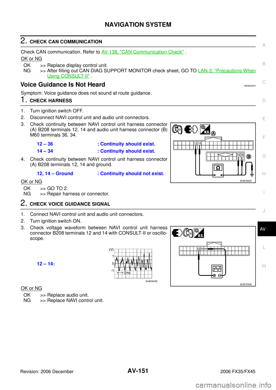
Voice Guidance Is Not HeardNKS003KY
Symptom: Voice guidance does not sound at route guidance.
1. CHECK HARNESS
1. Turn ignition switch OFF.
2. Disconnect NAVI control unit and audio unit connectors.
3. Check continuity between NAVI control unit harness connector (A) B208 terminals 12, 14 and audio unit harness connector (B)
M60 terminals 36, 34.
4. Check continuity between NAVI control unit harness connector (A) B208 terminals 12, 14 and ground.
OK or NG
OK >> GO TO 2.
NG >> Repair harness or connector.
2. CHECK VOICE GUIDANCE SIGNAL
1. Connect NAVI control unit and audio unit connectors.
2. Turn ignition switch ON.
3. Check voltage waveform between NAVI control unit harness connector B208 terminals 12 and 14 with CONSULT-II or oscillo-
scope.
OK or NG
OK >> Replace audio unit.
NG >> Replace NAVI control unit. 12 – 36 : Continuity should exist.
14 – 34 : Continuity should exist.
12, 14 – Ground : Continuity should not exist.
SKIB7865E
12 – 14:
SKIB7003ESKIB3609E
Page 761 of 4462
NAVIGATION SYSTEM AV-155
C
D E
F
G H
I
J
L
M A
B
AV
Revision: 2006 December 2006 FX35/FX45
Removal and Installation of NAVI Control UnitNKS003LK
REMOVAL
1. Remove passenger side seat. Refer to SE-97, "Removal and Installation" .
2. Remove clips (4), and remove NAVI control unit cover.
3. Remove screws (2) and nut (1) with power tool, and remove NAVI control unit.
4. Remove screws (4) with power tool and remove brackets.
INSTALLATION
Installation is the reverse order of removal.
Removal and Installation of GPS AntennaNKS003LL
REMOVAL
1. Remove audio unit. Refer to AV- 4 3 , "Removal and Installation of
Audio Unit" .
2. Remove screw (1) and remove GPS antenna.
INSTALLATION
Installation is the reverse order of removal.
PKIA3129E
SKIA5822E
SKIA5823E
SKIA5824E
Page 762 of 4462
AV-156
NAVIGATION SYSTEM
Revision: 2006 December 2006 FX35/FX45
Removal and Installation of A/C and AV SwitchNKS003LM
For A/C and AV switch removal and installation procedures, refer to AV- 4 4 , "Removal and Installation for A/C
and AV Switch" .
Removal and Installation of Display UnitNKS003LN
For display unit removal and installation procedures, refer to AV- 4 3 , "Disassembly and Assembly for Audio
Unit" .
Removal and Installation of Display Control UnitNKS003LO
For display control unit removal and installation procedures, refer to AV- 9 2 , "Removal and Installation of Dis-
play Control Unit"