2006 HYUNDAI TUCSON coolant temperature
[x] Cancel search: coolant temperaturePage 228 of 289

6
DO-IT-YOURSELF MAINTENANCE
9
!
!
WARNING:
The cooling fan is controlled by engine
coolant temperature and may sometimes
operate even when the engine is not run-
ning. Use extreme caution when working
near the blades of the coolant fan so that
you are not injured by a rotating fan blade.
As the engine coolant temperature de-
creases, the fan will automatically shut off.
This is a normal condition. 2. Turn the radiator cap counterclockwise with-
out pressing down on it, until it stops. This
relieves any pressure remaining in the cool-
ing system. And remove the radiator cap by
pushing down and turning counterclock-
wise.
3. Be sure your drain receptacle is in place.
Open the drain cock on the radiator. Allow all
the engine coolant to drain from the cooling
system, then securely close the drain cock.
4. Check Section 9 for the capacity of the
cooling system in your car. Then, following
the manufacturer's directions on the engine
coolant container, add the appropriate quan-
tity of coolant to the radiator.
5. Fill the radiator with clean demineralized or
distilled water. Continue to add clean dem-
ineralized or distilled water in small quantities
until the fluid level stays up in the radiator
neck.6. Start the engine, top off the radiator with
water and then add coolant to the reservoir
until the level is between "L" and "F".
7. Replace the radiator and reservoir caps and
check to be sure the drain cocks are fully
closed and not leaking.
G050D02A-AATTo Change the Engine CoolantThe engine coolant should be changed at those
intervals specified in the vehicle maintenance
schedule in Section 5.
HJM5034G050D01JM
CAUTION:
Engine coolant can damage the finish of
your car. If you spill engine coolant on the
car, wash it off thoroughly with clean water.
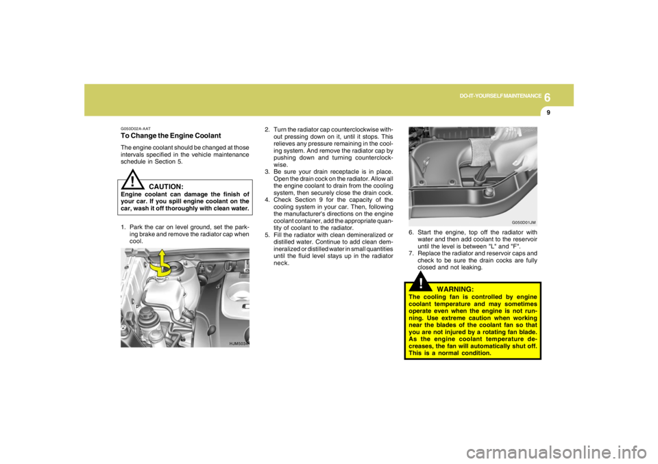
1. Park the car on level ground, set the park-
ing brake and remove the radiator cap when
cool.
Page 233 of 289

6
DO-IT-YOURSELF MAINTENANCE
14
HJM5011
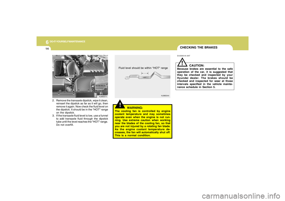
2. Remove the transaxle dipstick, wipe it clean,
reinsert the dipstick as far as it will go, then
remove it again. Now check the fluid level on
the dipstick. It should be in the "HOT" range
on the dipstick.
3. If the transaxle fluid level is low, use a funnel
to add transaxle fluid through the dipstick
tube until the level reaches the "HOT" range.
Do not overfill.
HJM5044
CHECKING THE BRAKES
!
WARNING:
The cooling fan is controlled by engine
coolant temperature and may sometimes
operate even when the engine is not run-
ning. Use extreme caution when working
near the blades of the cooling fan, so that
you are not injured by a rotating fan blade.
As the engine coolant temperature de-
creases, the fan will automatically shut off.
This is a normal condition.Fluid level should be within "HOT" range
G120A01A-AAT
CAUTION:
Because brakes are essential to the safe
operation of the car, it is suggested that
they be checked and inspected by your
Hyundai dealer. The brakes should be
checked and inspected for wear at those
intervals specified in the vehicle mainte-
nance schedule in Section 5.
!
Page 243 of 289

6
DO-IT-YOURSELF MAINTENANCE
24
POWER STEERING FLUID LEVELG230A03A-AAT
G220C01A-AAT
Checking Condenser Cooling FanThe condenser cooling fan should come on
automatically whenever the air conditioning is in
operation.
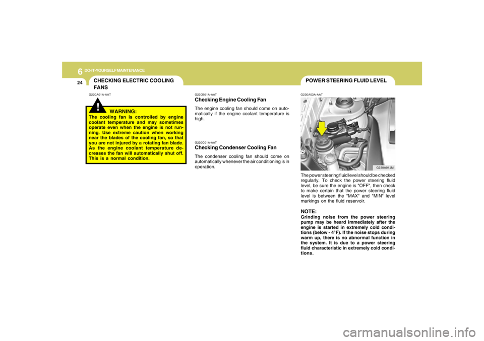
The power steering fluid level should be checked
regularly. To check the power steering fluid
level, be sure the engine is "OFF", then check
to make certain that the power steering fluid
level is between the "MAX" and "MIN" level
markings on the fluid reservoir.
NOTE:Grinding noise from the power steering
pump may be heard immediately after the
engine is started in extremely cold condi-
tions (below - 4°F). If the noise stops during
warm up, there is no abnormal function in
the system. It is due to a power steering
fluid characteristic in extremely cold condi-
tions.
G220B01A-AATChecking Engine Cooling FanThe engine cooling fan should come on auto-
matically if the engine coolant temperature is
high.
CHECKING ELECTRIC COOLING
FANS!
G220A01A-AAT
WARNING:
The cooling fan is controlled by engine
coolant temperature and may sometimes
operate even when the engine is not run-
ning. Use extreme caution when working
near the blades of the cooling fan, so that
you are not injured by a rotating fan blade.
As the engine coolant temperature de-
creases the fan will automatically shut off.
This is a normal condition.
G230A01JM
Page 259 of 289

7
EMISSION CONTROL SYSTEMS2
EMISSION CONTROL SYSTEM
H010D01A-AAT3. Exhaust Emission Control SystemThe Exhaust Emission Control System is a
highly effective system which controls exhaust
emissions while maintaining good vehicle
performace.
H010B01A-AAT1. Crankcase Emission Control
SystemThe positive crankcase ventilation system is
employed to prevent air pollution caused by
blow-by gases being emitted from the crank-
case. This system supplies filtered air to the
crankcase through the air intake hose. Inside
the crankcase, the fresh air mixes with blow-by
gases, which then pass through the PCV valve
and into the induction system.
H010A02O-AATYour Hyundai is equipped with an emission
control system to meet all requirements of the
U.S. Environmental Protection Agency or Cali-
fornia Air Resources Board.
There are three emission control systems which
are as follows.
(1) Crankcase emission control system
(2) Evaporative emission control system
(3) Exhaust emission control system
In order to assure the proper function of the
emission control systems, it is recommended
that you have your car inspected and main-
tained by an authorized Hyundai dealer in ac-
cordance with the maintenance schedule in this
manual.
Caution for the Inspection and Maintenance
Test (V6 Vehicle with Traction Control Sys-
tem)
o To prevent the vehicle from misfiring
during dynamometer testing, discon-
nect the ABS connector in the engine
compartment. (2.7 V6 only)
o For more information, see shop manual
(Wheel Speed Sensor).
o After dynamometer testing is completed,
erase the ABS/TCS DTC (Diagnotic
Trouble Code) with a GST (Generic Scan
Tool) or Hi-Scan Pro.
CanisterFuel vapors generated inside the fuel tank are
absorbed and stored in the canister. When the
engine is running, the fuel vapors absorbed in
the canister are drawn into the induction system
through the purge control solenoid valve.Purge Control Solenoid Valve (PCSV)The purge control solenoid valve is controlled
by the Engine Control Module (ECM); when the
engine coolant temperature is low during idling,
the PCSV closes so that evaporated fuel is not
taken into the engine. After the engine warms-
up during ordinary driving, the PCSV opens to
introduce evaporated fuel to the engine.
H010C01S-AAT2. Evaporative Emission Control (Includ-
ing ORVR: Onboard Refueling Vapor
Recovery) SystemThe Evaporative Emission Control System is
designed to prevent fuel vapors from escaping
into the atmosphere.
(The ORVR system is designed to allow the
vapors from the fuel tank to be loaded into a
canister while refueling at the gas station, pre-
venting the escape of fuel vapors into the
atmosphere.)
jmhma-7.p653/9/2005, 2:52 PM 2
Page 284 of 289

10
INDEX
3
Consumer Information......................................................................8-14
Cooling Fans.....................................................................................6-24
Corrosion protection
Cleaning the interior....................................................................... 4-5
Protecting your Hyundai from corrosion....................................... 4-2
Washing and waxing...................................................................... 4-3
Cruise Control...................................................................................1-85
D
Defrosting / Defogging ......................................................................1-96
Door
Central door lock............................................................................ 1-7
Door locks...................................................................................... 1-4
Front door edge warning light ......................................................1-84
Drink Holder ......................................................................................1-65
Drive Belts.........................................................................................6-20
Driving
Driving for economy .....................................................................2-22
Smooth cornering.........................................................................2-23
Winter driving...............................................................................2-23
E
Emission Control System ................................................................... 7-2
Engine
Before starting the engine .............................................................. 2-4
Compartment................................................................................. 6-2
Coolant........................................................................................... 6-8
Coolant temperature gauge .........................................................1-53
If the engine overheats .................................................................. 3-4Number........................................................................................... 8-2
Oil ................................................................................................... 6-5
Starting........................................................................................... 2-6
Engine Exhaust Can Be Dangerous .................................................. 2-2
F
4WD Lock System ............................................................................2-19
Fan Speed Control............................................................................1-89
Floor Mat Anchor ..............................................................................1-83
Fog Light
Front.............................................................................................1-61
Front Seats
Adjustable front seats ..................................................................1-12
Adjustable headrests...................................................................1-13
Adjusting seat forward and rearward ..........................................1-12
Adjusting seatback angle .............................................................1-13
Fuel
Capacity......................................................................................... 9-2
Gauge...........................................................................................1-53
Recommendations......................................................................... 1-2
Fuel Filler Lid
Remote release............................................................................1-80
Full-time 4WD Operation..................................................................2-16
Fuses ................................................................................................6-21
Fuse panel description......................................................................6-35
G
General Checks.................................................................................. 6-4
Glove Box..........................................................................................1-70