2006 HYUNDAI TUCSON engine
[x] Cancel search: enginePage 243 of 289
6
DO-IT-YOURSELF MAINTENANCE
24
POWER STEERING FLUID LEVELG230A03A-AAT
G220C01A-AAT
Checking Condenser Cooling FanThe condenser cooling fan should come on
automatically whenever the air conditioning is in
operation.
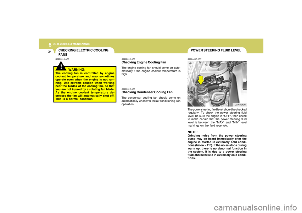
The power steering fluid level should be checked
regularly. To check the power steering fluid
level, be sure the engine is "OFF", then check
to make certain that the power steering fluid
level is between the "MAX" and "MIN" level
markings on the fluid reservoir.
NOTE:Grinding noise from the power steering
pump may be heard immediately after the
engine is started in extremely cold condi-
tions (below - 4°F). If the noise stops during
warm up, there is no abnormal function in
the system. It is due to a power steering
fluid characteristic in extremely cold condi-
tions.
G220B01A-AATChecking Engine Cooling FanThe engine cooling fan should come on auto-
matically if the engine coolant temperature is
high.
CHECKING ELECTRIC COOLING
FANS!
G220A01A-AAT
WARNING:
The cooling fan is controlled by engine
coolant temperature and may sometimes
operate even when the engine is not run-
ning. Use extreme caution when working
near the blades of the cooling fan, so that
you are not injured by a rotating fan blade.
As the engine coolant temperature de-
creases the fan will automatically shut off.
This is a normal condition.
G230A01JM
Page 244 of 289
6
DO-IT-YOURSELF MAINTENANCE
25
HEADLIGHT AIMING ADJUSTMENT
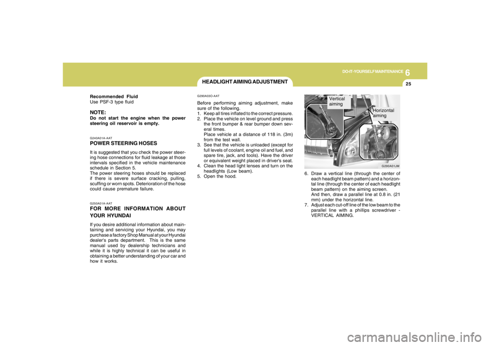
6. Draw a vertical line (through the center of
each headlight beam pattern) and a horizon-
tal line (through the center of each headlight
beam pattern) on the aiming screen.
And then, draw a parallel line at 0.8 in. (21
mm) under the horizontal line.
7. Adjust each cut-off line of the low beam to the
parallel line with a phillips screwdriver -
VERTICAL AIMING.
G290A03O-AATBefore performing aiming adjustment, make
sure of the following.
1. Keep all tires inflated to the correct pressure.
2. Place the vehicle on level ground and press
the front bumper & rear bumper down sev-
eral times.
Place vehicle at a distance of 118 in. (3m)
from the test wall.
3. See that the vehicle is unloaded (except for
full levels of coolant, engine oil and fuel, and
spare tire, jack, and tools). Have the driver
or equivalent weight placed in driver's seat.
4. Clean the head light lenses and turn on the
headlights (Low beam).
5. Open the hood.
G250A01A-AATFOR MORE INFORMATION ABOUT
YOUR HYUNDAIIf you desire additional information about main-
taining and servicing your Hyundai, you may
purchase a factory Shop Manual at your Hyundai
dealer's parts department. This is the same
manual used by dealership technicians and
while it is highly technical it can be useful in
obtaining a better understanding of your car and
how it works.G240A01A-AATPOWER STEERING HOSESIt is suggested that you check the power steer-
ing hose connections for fluid leakage at those
intervals specified in the vehicle maintenance
schedule in Section 5.
The power steering hoses should be replaced
if there is severe surface cracking, pulling,
scuffing or worn spots. Deterioration of the hose
could cause premature failure. Recommended Fluid
Use PSF-3 type fluidNOTE:Do not start the engine when the power
steering oil reservoir is empty.
G290A01JM
Vertical
aiming
Horizontal
aiming
Page 246 of 289
6
DO-IT-YOURSELF MAINTENANCE
27
REPLACEMENT OF LIGHT BULBS!
G260A02A-AATBefore attempting to replace a light bulb, be sure
the switch is turned to the "OFF" position.
The next paragraph shows how to reach the
light bulbs so they may be changed. Be sure to
replace the burned-out bulb with one of the
same number and wattage rating.
See page 6-34 for the wattage description.
CAUTION:
o Keep the lamps out of contact with pe-
troleum products, such as oil, gasoline,
etc.
o After heavy, driving rain or washing,
headlight and taillight lenses could ap-
pear frosty. This condition is caused by
the temperature difference between the
lamp inside and outside. This is similar
to the condensation on your windows
inside your vehicle during the rain and
doesn’t indicate a problem with your
vehicle. If the water leaks into the lamp
bulb circuitry, have the vehicle checked
by an Authorized Hyundai Dealer.
HJM5013 G270A02O-AAT
Headlight and Front Turn Signal Light1. Allow the bulb to cool. Wear eye protection.
2. Open the engine hood.
3. Always grasp the bulb by its plastic base,
avoid touching the glass.
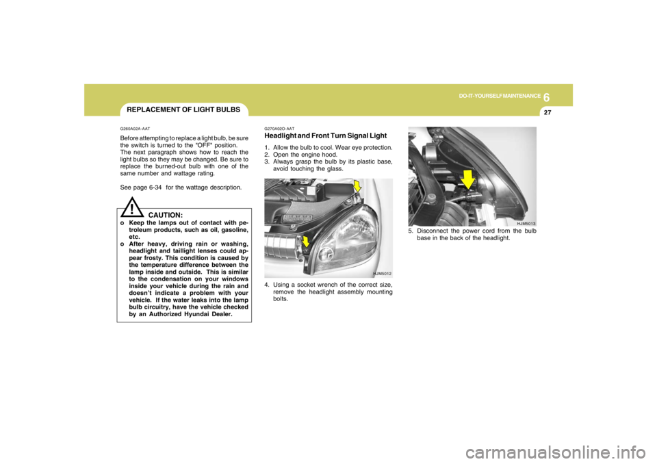
4. Using a socket wrench of the correct size,
remove the headlight assembly mounting
bolts.
HJM5012
5. Disconnect the power cord from the bulb
base in the back of the headlight.
Page 254 of 289

6
DO-IT-YOURSELF MAINTENANCE
35
FUSE PANEL DESCRIPTIONG200C01JM-GATEngine Compartment
G200C01JM
NOTE:Not all fuse panel descriptions in this manual may be applicable to your vehicle. It is accurate at the time of printing. When you inspect the
fuse box on your vehicle, refer to the fuse box label.FUSE
RATING
30A
30A
50A
50A
30A
40A
30A
30A
15A
10A
15A
15A
15A
15A
15A
15APROTECTED COMPONENTS
Start relay, Ignition switch
Engine control, Fuel pump , A/C, Generator, ATM
Ignition switch, Power connector
Cooling fan
ABS, ESC
ABS, ESC
Blower
Ignition switch, Power connector
Injector
Cooling fan, Stop lamp switch, Oxygen sensor, ECM/PCM
DRL
Front fog lamp
Horn, Siren
A/C
Head lamp (HIGH)
Head lamp (LOW)
IGN
ECU
BATT #1
C/FAN
ABS #1
ABS #2
BLOWER
BATT #2
INJ
SNSR
DRL
F/FOG
HORN
A/CON
H/LP (HI)
H/LP (LOW) FUSIBLE
LINK
FUSE
DESCRIPTION
Page 259 of 289

7
EMISSION CONTROL SYSTEMS2
EMISSION CONTROL SYSTEM
H010D01A-AAT3. Exhaust Emission Control SystemThe Exhaust Emission Control System is a
highly effective system which controls exhaust
emissions while maintaining good vehicle
performace.
H010B01A-AAT1. Crankcase Emission Control
SystemThe positive crankcase ventilation system is
employed to prevent air pollution caused by
blow-by gases being emitted from the crank-
case. This system supplies filtered air to the
crankcase through the air intake hose. Inside
the crankcase, the fresh air mixes with blow-by
gases, which then pass through the PCV valve
and into the induction system.
H010A02O-AATYour Hyundai is equipped with an emission
control system to meet all requirements of the
U.S. Environmental Protection Agency or Cali-
fornia Air Resources Board.
There are three emission control systems which
are as follows.
(1) Crankcase emission control system
(2) Evaporative emission control system
(3) Exhaust emission control system
In order to assure the proper function of the
emission control systems, it is recommended
that you have your car inspected and main-
tained by an authorized Hyundai dealer in ac-
cordance with the maintenance schedule in this
manual.
Caution for the Inspection and Maintenance
Test (V6 Vehicle with Traction Control Sys-
tem)
o To prevent the vehicle from misfiring
during dynamometer testing, discon-
nect the ABS connector in the engine
compartment. (2.7 V6 only)
o For more information, see shop manual
(Wheel Speed Sensor).
o After dynamometer testing is completed,
erase the ABS/TCS DTC (Diagnotic
Trouble Code) with a GST (Generic Scan
Tool) or Hi-Scan Pro.
CanisterFuel vapors generated inside the fuel tank are
absorbed and stored in the canister. When the
engine is running, the fuel vapors absorbed in
the canister are drawn into the induction system
through the purge control solenoid valve.Purge Control Solenoid Valve (PCSV)The purge control solenoid valve is controlled
by the Engine Control Module (ECM); when the
engine coolant temperature is low during idling,
the PCSV closes so that evaporated fuel is not
taken into the engine. After the engine warms-
up during ordinary driving, the PCSV opens to
introduce evaporated fuel to the engine.
H010C01S-AAT2. Evaporative Emission Control (Includ-
ing ORVR: Onboard Refueling Vapor
Recovery) SystemThe Evaporative Emission Control System is
designed to prevent fuel vapors from escaping
into the atmosphere.
(The ORVR system is designed to allow the
vapors from the fuel tank to be loaded into a
canister while refueling at the gas station, pre-
venting the escape of fuel vapors into the
atmosphere.)
jmhma-7.p653/9/2005, 2:52 PM 2
Page 260 of 289
7
EMISSION CONTROL SYSTEMS
3
CATALYTIC CONVERTER
!
WARNING:
o Use unleaded fuel only.
o Maintain the engine in good operating
condition. Extremely high catalytic con-
verter temperatures can result from im-
proper operation of the electrical, igni-
tion or multiport electronic fuel injec-
tion.
o If your engine stalls, pings, knocks, or is
hard to start, have your Hyundai dealer
inspect and repair the problem as soon
as possible.
o Avoid driving with a very low fuel level.
Running out of gasoline may cause the
engine to misfire and result in damage to
the catalytic converter.
o Avoid idling the engine for periods
longer than 10 minutes.
o The vehicle should not be pushed or
pulled to get started. This may cause the
catalytic converter to overheat and cre-
ate a fire hazard.
o Do not touch the catalytic converter or
any other part of the exhaust system
while the catalytic converter is hot. Shut
off the engine, wait for at least one hour
before touching the catalytic converter
or any other part of the exhaust system.
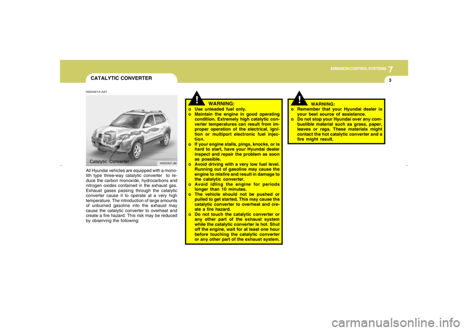
H020A01A-AATAll Hyundai vehicles are equipped with a mono-
lith type three-way catalytic converter to re-
duce the carbon monoxide, hydrocarbons and
nitrogen oxides contained in the exhaust gas.
Exhaust gases passing through the catalytic
converter cause it to operate at a very high
temperature. The introduction of large amounts
of unburned gasoline into the exhaust may
cause the catalytic converter to overheat and
create a fire hazard. This risk may be reduced
by observing the following:
H020A01JM
Catalytic Converter
!
WARNING:
o Remember that your Hyundai dealer is
your best source of assistance.
o Do not stop your Hyundai over any com-
bustible material such as grass, paper,
leaves or rags. These materials might
contact the hot catalytic converter and a
fire might result.
jmhma-7.p653/9/2005, 2:52 PM 3
Page 261 of 289
Vehicle Identification Number (VIN) .............................. 8-2
Engine Number ............................................................. 8-2
Tire Information ............................................................. 8-2
Recommended Inflation Pressures ............................... 8-3
Tire Sidewall Labeling ................................................... 8-6
Tire Terminology and Definitions ................................... 8-7
Snow Tires..................................................................8-10
Tire Chains ..................................................................8-10
Tire Rotation................................................................8-11
Tire Balancing.............................................................8-11
Tire Traction................................................................8-11
When to Replace Tires ...............................................8-12
Tire Maintenance........................................................8-13
Spare Tire and Tools ...................................................8-14
Warranties for Your Hyundai Vehicle..........................8-14
Consumer Information.................................................8-14
Reporting Safety Defects............................................8-17
Binding Arbitration of Warranty Claims (U.S.A Only) .. 8-17
CONSUMER INFORMATION, REPORTING
SAFETY DEFECTS & BINDING
ARBITRATION OF WARRANTY CLAIMS
8
8
Page 262 of 289
8
CONSUMER INFORMATION, REPORTING SAFETY DEFECTS & BINDING ARBITRATION OF WARRANTY CLAIMS2
ENGINE NUMBER
VEHICLE IDENTIFICATION
NUMBER (VIN)
I010B01A-AAT I010A02JM-AAT
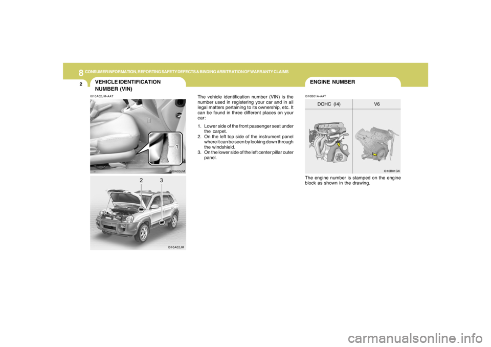
The vehicle identification number (VIN) is the
number used in registering your car and in all
legal matters pertaining to its ownership, etc. It
can be found in three different places on your
car:
1. Lower side of the front passenger seat under
the carpet.
2. On the left top side of the instrument panel
where it can be seen by looking down through
the windshield.
3. On the lower side of the left center pillar outer
panel.
The engine number is stamped on the engine
block as shown in the drawing.
I010A03JMI010B01GK
V6 DOHC (I4)
I010A02JM