2006 Hyundai Terracan ECU
[x] Cancel search: ECUPage 453 of 539
3
IN CASE OF EMERGENCY
7
!
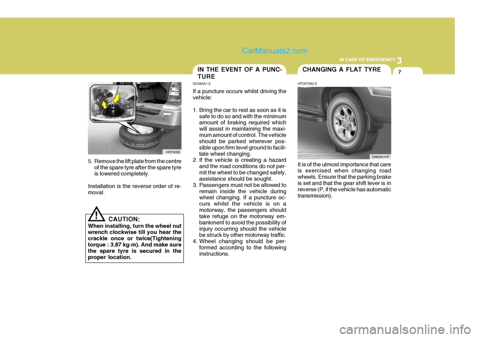
5. Remove the lift plate from the centre
of the spare tyre after the spare tyre is lowered completely.
Installation is the reverse order of re-moval.
CAUTION:
When installing, turn the wheel nutwrench clockwise till you hear the crackle once or twice(Tighteningtorque : 3.87 kg·m). And make sure the spare tyre is secured in the proper location. It is of the utmost importance that care is exercised when changing road wheels. Ensure that the parking brakeis set and that the gear shift lever is in reverse (P, if the vehicle has automatic transmission).
HHP4026
IN THE EVENT OF A PUNC- TURE
SD060A1-E If a puncture occurs whilst driving the vehicle:
1. Bring the car to rest as soon as it is
safe to do so and with the minimum amount of braking required which will assist in maintaining the maxi-mum amount of control. The vehicle should be parked wherever pos- sible upon firm level ground to facili-tate wheel changing.
2. If the vehicle is creating a hazard
and the road conditions do not per-mit the wheel to be changed safely, assistance should be sought.
3. Passengers must not be allowed to remain inside the vehicle duringwheel changing. If a puncture oc- curs whilst the vehicle is on amotorway, the passengers should take refuge on the motorway em- bankment to avoid the possibility ofinjury occurring should the vehicle be struck by other motorway traffic.
4. Wheel changing should be per- formed according to the followinginstructions.CHANGING A FLAT TYRE
HPD070A2-E
D060A01HP
Page 460 of 539
3 IN CASE OF EMERGENCY
14
D060J02O-EAT AFTER CHANGING WHEELS If you have a tyre gauge, remove the valve cap and check the air pressure.If the pressure is lower than recom- mended, drive slowly to the nearest service station and inflate to the cor-rect pressure. If it is too high, adjust it until it is correct. Always reinstall the valve cap after checking or adjustingtyre pressure. If the cap is not re- placed, air may leak from the tyre. If you lose a valve cap, buy another andinstall it as soon as possible. After you have changed wheels, al- ways secure the flat tyre in its placeand return the jack and tools to their proper storage locations.
HHP5019
IF YOUR VEHICLE MUST BE TOWED
D080A02HR-GAT If your vehicle has to be towed, it should be done by your Hyundai authorisedrepairer or a commercial tow truck ser- vice. This will help assure that your vehicle is not damaged in towing. Also,professionals are generally aware of local laws governing towing. In any case, rather than risk damage to yourcar, it is suggested that you show this information to the tow truck operator. Be sure that a safety chain system isused and that all local laws are ob- served. It is recommended that your vehicle betowed with a wheel lift and dollies or flatbed equipment with all the wheels off the ground.
! CAUTION:
o Your vehicle can be damaged if towed incorrectly!
o Be sure the transmission is in neutral.
o When the engine will not start, be
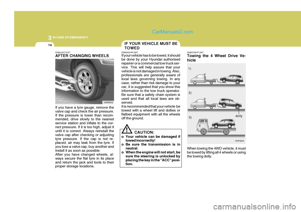
sure the steering is unlocked by placing the key in the "ACC" posi- tion. D080C02HP-GAT Towing the 4 Wheel Drive Ve- hicle
HHP4044
When towing the 4WD vehicle, it must be towed by lifting all 4 wheels or using the towing dolly. 1)
2)
3)
dolly
Page 475 of 539
5
VEHICLE MAINTENANCE REQUIREMENTS
7
!
F060B01A-EAT
o Drive belts
Inspect all drive belts for evidence of cuts, cracks, excessive wear or oil contamination and replace if neces-sary. Drive belts should be checked periodically for proper tension and ad- justed as necessary. F060C01A-AAT
o Fuel filter
A clogged filter can limit the speed at
which the vehicle may be driven, dam- age the emission system and cause hard starting. If an excessive amountof foreign matter accumulates in the fuel tank, the filter may require re- placement more frequently. After installing a new filter, run the
engine for several minutes, and checkfor leaks at the connections. Fuel fil- ters should be installed by trained technicians.
F060D01TB-EAT
o Fuel lines, fuel hoses and con- nections
Check the fuel lines, fuel hoses and
connections for leakage and damage. Have a trained technician replace anydamaged or leaking parts immediately. WARNING (Diesel only):
Never work on injection system withengine running or within 30 sec-onds after shutting off engine. High pressure pump, rail, injectors and high pressure pipes are subject tohigh pressure even after the engine stopped. The fuel jet produced by fuel leaks may cause serious injury,if it contacts the body. People using pacemakers should ensure that they keep a distance of 30cm from theECU or wiring harness within the engine room while engine is run- ning, since the high currents in theCommon Rail system produce con- siderable magnetic fields.
EXPLANATION OF SCHED- ULED MAINTENANCE ITEMS
F060M01A-AAT
o Engine oil and filter
The engine oil and filter should be
changed at the intervals specified in the maintenance schedule. If the car is being driven in severe conditions,more frequent oil and filter changes are required.
Page 476 of 539

5VEHICLE MAINTENANCE REQUIREMENTS
8
F060E01A-AAT
o Timing belt Inspect all parts related to the timing belt for damage and deformation. Replace any damaged parts immedi- ately. F060G01A-EAT
o Vapour hose and fuel filler cap The vapour hose and fuel filler cap should be inspected at those intervals specified in the maintenance sched-ule. Make sure that a new vapour hose or fuel filler cap is correctly replaced. F060F02A-AAT
o Crankcase ventilation hoses
Inspect the surface of hoses for evi-
dence of heat and/or mechanical dam-age. Hard and brittle rubber, cracking, tears, cuts, abrasions, and excessiveswelling indicate deterioration. Particu- lar attention should be paid to examine those hose surfaces nearest to highheat sources, such as the exhaust manifold.
Inspect the hose routing to assure that
the hoses do not come in contact with any heat source, sharp edges or mov-ing component which might cause heat damage or mechanical wear. Inspect all hose connections, such as clampsand couplings, to make sure they are secure, and that no leaks are present. Hoses should be replaced immedi-ately if there is any evidence of dete- rioration or damage. F060H01A-AAT
o Air cleaner filter
A Genuine Hyundai air cleaner filter is
recommended when the filter is re-placed.
F060J01A-EAT
o Spark plugs (For petrol engine)
Make sure to install new spark plugs
of the correct heat range. F070B01A-AAT
o Cooling system
Check the cooling system, such as radiator, coolant reservoir, hoses andconnections for leakage and damage. Replace any damaged parts.
Page 486 of 539
6 OWNER MAINTENANCE
8
!
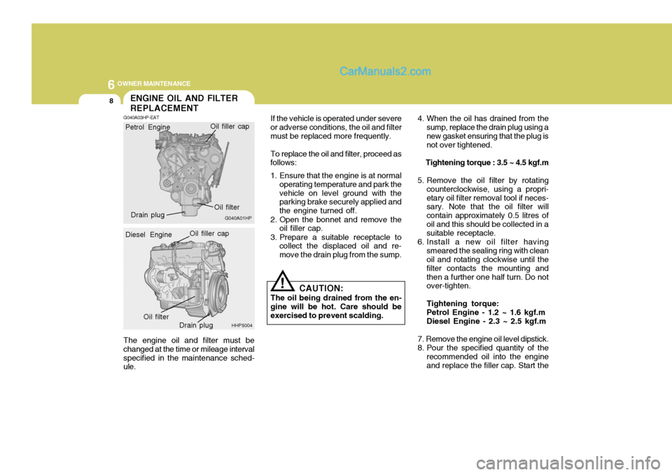
The engine oil and filter must be changed at the time or mileage intervalspecified in the maintenance sched- ule. If the vehicle is operated under severe
or adverse conditions, the oil and filter must be replaced more frequently.
To replace the oil and filter, proceed as
follows:
1. Ensure that the engine is at normal
operating temperature and park the vehicle on level ground with the parking brake securely applied and the engine turned off.
2. Open the bonnet and remove the oil filler cap.
3. Prepare a suitable receptacle to collect the displaced oil and re-move the drain plug from the sump. 4. When the oil has drained from the
sump, replace the drain plug using anew gasket ensuring that the plug is not over tightened.
Tightening torque : 3.5 ~ 4.5 kgf.m
5. Remove the oil filter by rotating counterclockwise, using a propri- etary oil filter removal tool if neces- sary. Note that the oil filter will contain approximately 0.5 litres ofoil and this should be collected in a suitable receptacle.
6. Install a new oil filter having smeared the sealing ring with cleanoil and rotating clockwise until the filter contacts the mounting andthen a further one half turn. Do not over-tighten. Tightening torque: Petrol Engine - 1.2 ~ 1.6 kgf.m Diesel Engine - 2.3 ~ 2.5 kgf.m
7. Remove the engine oil level dipstick.
8. Pour the specified quantity of the recommended oil into the engine and replace the filler cap. Start the
CAUTION:
The oil being drained from the en-
gine will be hot. Care should be exercised to prevent scalding.
ENGINE OIL AND FILTER REPLACEMENT
G040A03HP-EAT
G040A01HP
Petrol Engine
Oil filter
Drain plug Oil filler cap
HHP5004
Diesel Engine
Oil filler capOil filter
Drain plug
Page 496 of 539

6 OWNER MAINTENANCE
18
!
!!WARNING (Diesel only):
Never work on injection system with
engine running or within 30 sec- onds after shutting off engine. Highpressure pump, rail, injectors and high pressure pipes are subject to high pressure even after the enginestopped. The fuel jet produced by fuel leaks may cause serious injury, if it contacts the body. People usingpacemakers should ensure that they keep a distance of 30cm from the ECU or wiring harness within theengine room whilst engine is run- ning, since the high currents in the Common Rail system produce con-siderable magnetic fields.
WARNING:
The electric engine cooling fan au-
tomatically switches on and off ac- cording to engine temperature. Be careful to keep away from the fanduring this check as it may switch on at any time.
NOTE: Only lint free cloth should be used
for wiping the dipstick. The pres- ence of lint within the transmis- sion may cause problems with the normal function of the transmis-sion. CAUTION:
Correct operation of the braking
system is essential to the safe op- eration of the vehicle and there- fore, any maintenance operationsother than those listed below should be entrusted to a Hyundai authorised repairer.
SG120C2-E
Brake Fluid Recommendations
Only brake fluid conforming to DOT 3
or DOT 4 specifications or highermay be used in the braking system. Care should be taken to observe the instructions and precautions printedupon the container.
BRAKE SYSTEM CHECKING
SG120A1-E
Page 521 of 539
7
EMISSION CONTROL SYSTEMS
3
DH010B1-E
1. Crankcase Emission Control System ; For a Petrol Engine
The positive crankcase ventilation
(PVC) system is employed to prevent air pollution caused by blow-by gases being emitted from the crankcase.
This system supplies fresh air to the
crankcase through the air cleaner.Inside the crankcase, the fresh airmixes with blow-by gases, then passes through the PCV valve into the intake system.
ZH010C1-E
2. Evaporative Emission Control System ; For a Petrol Engine
The Evaporative Emission Control
System is designed to prevent fuel vapors from escaping into the atmo- sphere. Canister
Whilst the engine is inoperative, fuel
vapors generated inside the fuel tank are absorbed and stored in the canis-ter. When the engine is running, the fuel vapors absorbed in the canister are drawn into the induction systemthrough the purge control solenoid valve. Purge Control Solenoid Valve
The purge control solenoid valve is
controlled by the ECU (Engine Control Unit); when the engine coolant tem- perature is low, and during idling, it closes, so that evaporated fuel is nottaken into the surge tank. After engine warm-up, during ordinary driving, it opens to introduce evaporated fuel tothe surge tank.
SH010D1-E
3. Exhaust Emission Control System
The exhaust emission control system
is a highly effective system which controls exhaust emission while main- taining good vehicle performance.
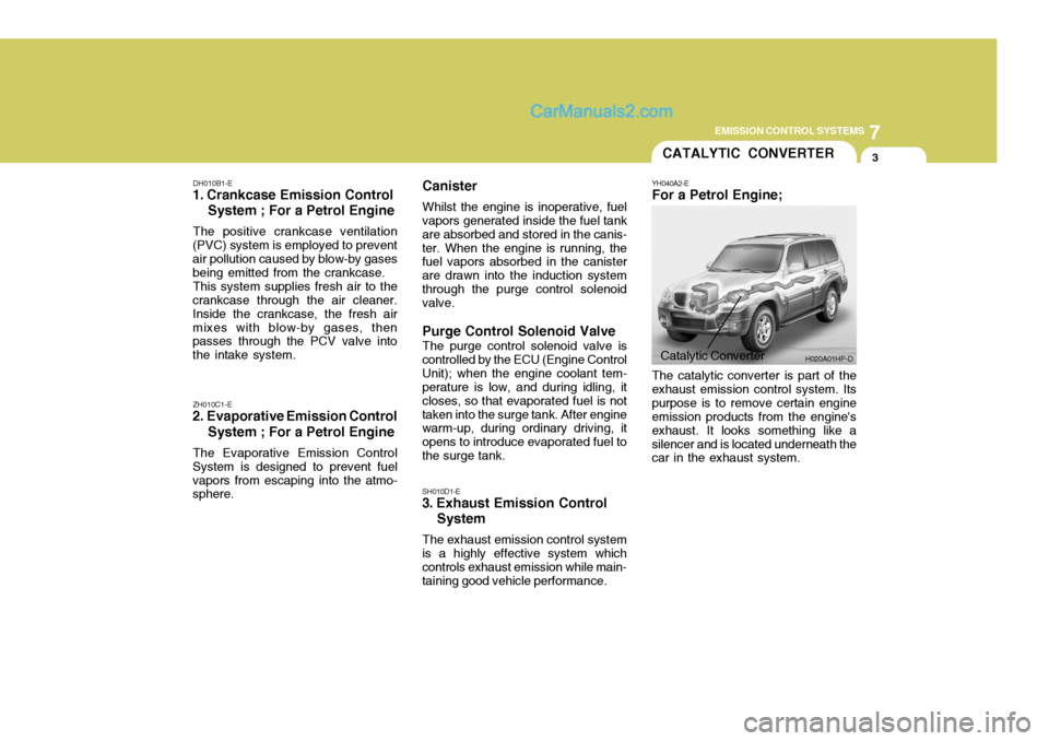
Catalytic Converter H020A01HP-D
CATALYTIC CONVERTER
YH040A2-E For a Petrol Engine; The catalytic converter is part of the exhaust emission control system. Itspurpose is to remove certain engine emission products from the engine's exhaust. It looks something like asilencer and is located underneath the car in the exhaust system.
Page 537 of 539
10INDEX
4
J Jump Starting .............................................................. 3-3
K
Key ....................................................................... 1-5, 1-7
If you lose y our keys ............................................. 3-16
Positions ................................................................... 2-4
Keyless Entry System .............................................. 1-13
L
Limited-Slip Differential (LSD) ....................................2-22
Lubrication Chart .......................................................... 9-4
Luggage Compartment Cargo Security Screen ........................................... 1-80
Light ........................................................................ 1-79
Net .......................................................................... 1-79
MMaintenance Requirements Explanation of scheduled maintenance items .......... 5-7
Maintenance and servicing requirement s .................. 5-2
Maintenance under severe usage conditions ............ 5-6
Regular servici ng ...................................................... 5-3
Mirrors Interior rearview ...................................................... 1-77
Outside rearview ..................................................... 1-75
Multi Box ................................................................... 1-74Multi-Function Switch
Headlight flash ........................................................ 1-62
High and low beam ................................................. 1-61
Lane change si gnal ................................................. 1-60
Lighting switch ........................................................ 1-61
Sidelight auto cut .................................................... 1-61
Turn signal operation .............................................. 1-60
O Odometer ................................................................... 1-59
Outside Rearview Mirror ............................................ 1-75
P Parking Brake ............................................................ 1-78
Part-time 4WD Opera tion ........................................... 2-15
Power Driver's Seat ................................................... 1-19
Power Outlet .............................................................. 1-68
Power Steering Fluid Level ....... .................................6-29
R Rear Seat Adjustable head restraints ...................................... 1-22
Adjusting seatback angle ....................................... 1-22
Folding rear seatback and seat cushion .................1-23
Rear Seat Warning.................................................... 1-25
Rheostat Sw itch ........................................................ 1-67
Roof Bars .................................................................. 1-81
Running in Your New Hyundai ..................................... 1-4