Page 370 of 539
1CONTROLS AND EQUIPMENT
62FOG LIGHT SWITCH
B360B01Y-AAT Front Fog Light Switch To turn on the front fog lights, place the switch in the "ON" position. They will light when the headlight switch is in thefirst or second position. B360A01HP-GAT Rear Fog Light Switch
HHP2100-E B360A01HP-E
SB220E1-EHEADLIGHT FLASH The headlights may be flashed by pull- ing the turn signal switch lever towards the steering wheel. The headlights will be extinguished when the switch isreleased.
HHP2098-E
To turn on the rear fog lights, push the switch. They will light when the head- light switch is in the second position or the front fog light is turned on and thekey is in the "ON" position.
Page 385 of 539
1
CONTROLS AND EQUIPMENT
77
!
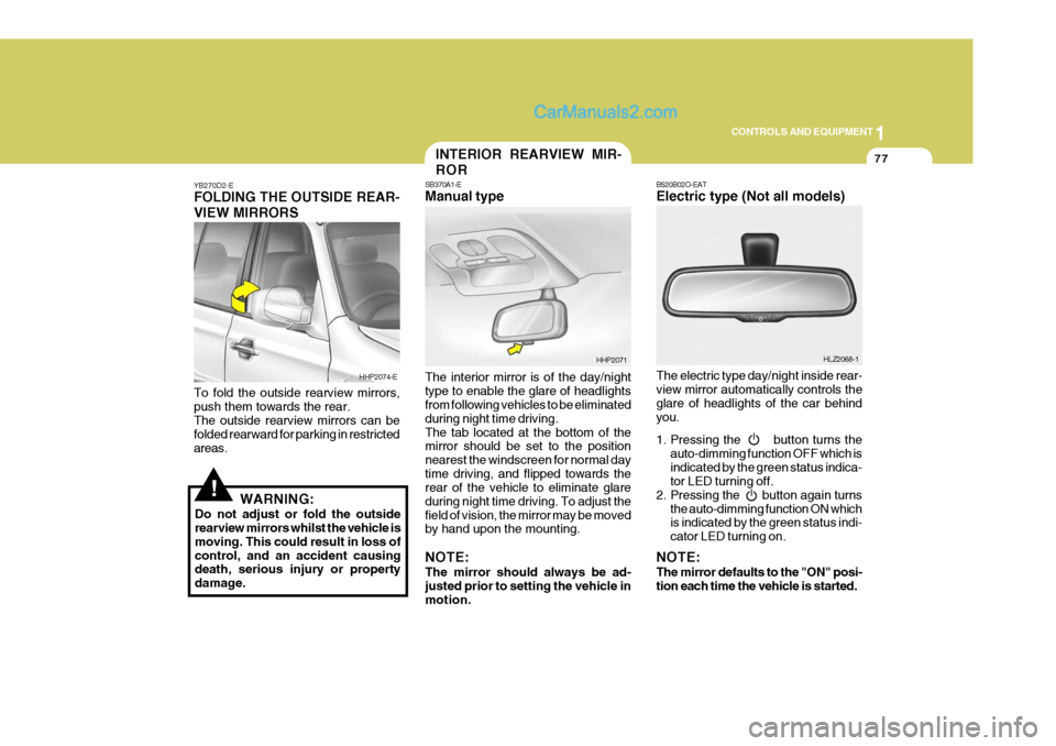
YB270D2-E FOLDING THE OUTSIDE REAR- VIEW MIRRORS To fold the outside rearview mirrors, push them towards the rear. The outside rearview mirrors can be folded rearward for parking in restrictedareas.
WARNING:
Do not adjust or fold the outside rearview mirrors whilst the vehicle is moving. This could result in loss ofcontrol, and an accident causing death, serious injury or property damage. The interior mirror is of the day/nighttype to enable the glare of headlights from following vehicles to be eliminated during night time driving.The tab located at the bottom of the mirror should be set to the position nearest the windscreen for normal daytime driving, and flipped towards the rear of the vehicle to eliminate glare during night time driving. To adjust thefield of vision, the mirror may be moved by hand upon the mounting. NOTE: The mirror should always be ad- justed prior to setting the vehicle in motion.
HHP2074-E
HHP2071
INTERIOR REARVIEW MIR- ROR
SB370A1-E Manual type
B520B02O-EAT Electric type (Not all models) The electric type day/night inside rear- view mirror automatically controls the glare of headlights of the car behindyou.
1. Pressing the button turns the
auto-dimming function OFF which is indicated by the green status indica- tor LED turning off.
2. Pressing the button again turns the auto-dimming function ON whichis indicated by the green status indi- cator LED turning on.
NOTE: The mirror defaults to the "ON" posi- tion each time the vehicle is started. HLZ2068-1
Page 394 of 539
1CONTROLS AND EQUIPMENT
86
!
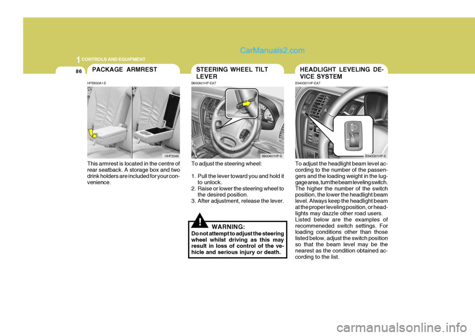
To adjust the steering wheel:
1. Pull the lever toward you and hold it
to unlock.
2. Raise or lower the steering wheel to the desired position.
3. After adjustment, release the lever.
WARNING:
Do not attempt to adjust the steering wheel whilst driving as this may result in loss of control of the ve- hicle and serious injury or death. To adjust the headlight beam level ac-cording to the number of the passen- gers and the loading weight in the lug- gage area, turn the beam leveling switch.The higher the number of the switch position, the lower the headlight beam level. Always keep the headlight beamat the proper leveling position, or head- lights may dazzle other road users. Listed below are the examples ofrecommeneded switch settings. For loading conditions other than those listed below, adjust the switch positionso that the beam level may be the nearest as the condition obtained ac- cording to the list.
STEERING WHEEL TILT LEVER
B600A01HP-EAT
B600A01HP-E
HEADLIGHT LEVELING DE- VICE SYSTEM
B340G01HP-EAT
B340G01HP-E
This armrest is located in the centre of rear seatback. A storage box and two drink holders are included for your con- venience.
PACKAGE ARMREST
HPB830A1-E
HHP2048
Page 479 of 539
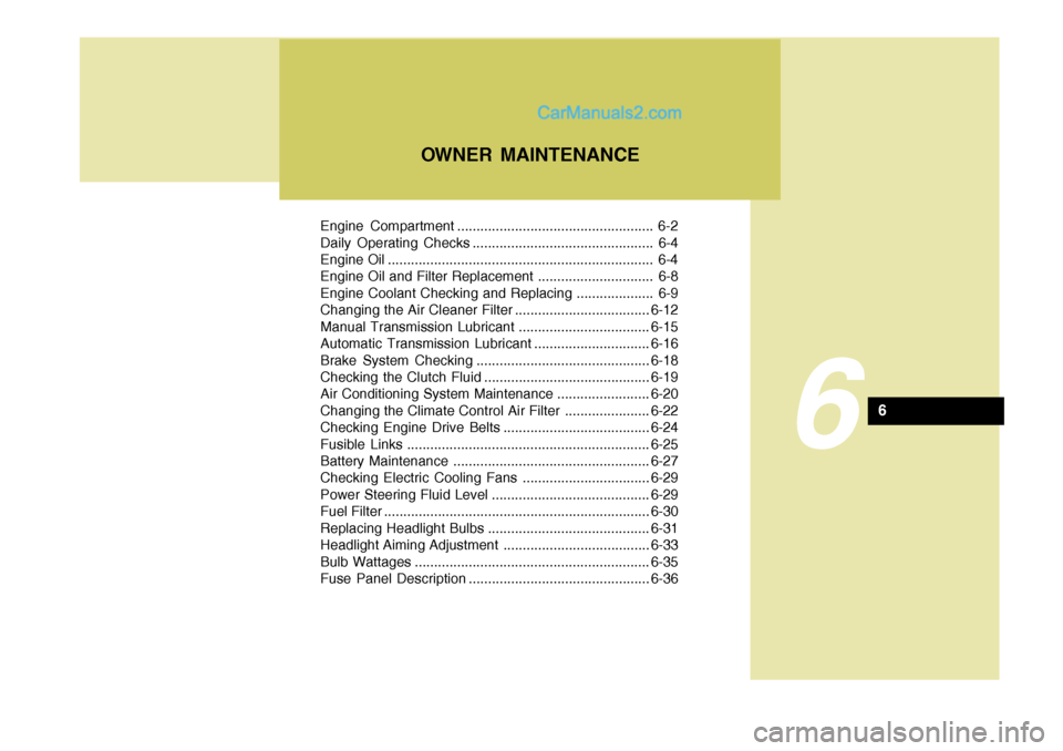
Engine Compartment ................................................... 6-2
Daily Operating Checks ............................................... 6-4
Engine Oil ..................................................................... 6-4
Engine Oil and Filter Replacement .............................. 6-8
Engine Coolant Checking and Replacing .................... 6-9
Changing the Air Cleaner Filter ...................................6-12
Manual Transmission Lubricant ..................................6-15
Automatic Transmission Lubricant ..............................6-16
Brake System Checking ............................................. 6-18
Checking the Clutch Fluid ........................................... 6-19
Air Conditioning System Maintenance ........................ 6-20
Changing the Climate Control Air Filter .. ....................6-22
Checking Engine Drive Belts ...................................... 6-24
Fusible Links ............................................................... 6-25
Battery Mai ntenance ................................................... 6-27
Checking Electric Cooling Fans .................................6-29
Power Steering Fluid Level ......................................... 6-29
Fuel Filter ..................................................................... 6-30
Replacing Headlight Bulbs .......................................... 6-31
Headlight Aiming Adjustment ...................................... 6-33
Bulb Wattages ............................................................. 6-35
Fuse Panel D escription ............................................... 6-36
OWNER MAINTENANCE
6
6
Page 505 of 539
6
OWNER MAINTENANCE
27
!WARNING:
Motor vehicle batteries contain sulphuric acid which is corrosive and poisonous. Hydrogen gas isemitted from the battery which is explosive when combined with oxygen. The following precautionsmust be strictly observed to avoid personal injury or damage to the vehicle.
BATTERY MAINTENANCE
DG210A2-E
HHP5020-E
G200C01HP-GAT
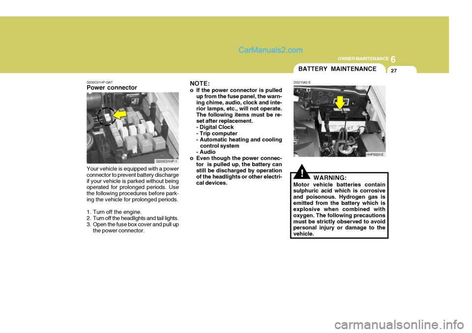
Power connector NOTE:
o If the power connector is pulled up from the fuse panel, the warn- ing chime, audio, clock and inte- rior lamps, etc., will not operate. The following items must be re-set after replacement.- Digital Clock - Trip computer
- Automatic heating and cooling
control system
- Audio
o Even though the power connec- tor is pulled up, the battery can still be discharged by operation of the headlights or other electri-cal devices.
Your vehicle is equipped with a powerconnector to prevent battery dischargeif your vehicle is parked without being operated for prolonged periods. Use the following procedures before park-ing the vehicle for prolonged periods.
1. Turn off the engine.
2. Turn off the headlights and tail lights.
3. Open the fuse box cover and pull up the power connector.
G200C01HP-1
Page 509 of 539

6
OWNER MAINTENANCE
31
!
!
3. Check to be sure that the warning
lamp illuminates when the ignition key is turned to "ON", and that it goes off when the engine is started. If in doubt, consult your nearest Hyundai authorised repairer.
NOTE: It is recommended that water accu- mulated in the fuel filter should be removed by a Hyundai authorised repairer.
WARNING:
Be sure to carefully wipe away anywater drained out in this manner, because the fuel mixed in the water might be ignited and resultin a fire. Before attempting to replace a head-
light bulb, be sure the switch is turned to the "OFF" position.
The next paragraph shows how to
reach the headlight bulbs so they may be changed. Be sure to replacethe burned-out bulb with one of the same number and wattage rating.
Ensure that the replacement bulb has
the same cap configuration and watt-age as the original.
See page 6-35 for the wattage descrip-
tions.
CAUTION:
Keep the lamps out of contact with
petroleum products, such as oil, petrol, etc.
REPLACING HEADLIGHT BULBS
G260A01HP-EAT
G300B02HP-EAT
Removal Of Water From TheFuel Filter (For Diesel Engine)
If the fuel filter warning lamp illumi- nates during driving, it indicates that water has accumulated in the fuel filter. If this occurs, remove the wateras described below.
1. Loosen the drain plug at the bot- tom of the fuel filter.
2. Tighten the drain plug when water no longer comes out.
HHP5047-E
Page 510 of 539
6 OWNER MAINTENANCE
32
7. Disconnect the connector from the
bulb base in the back of the head- light.
G270A02HP
8. Push the bulb spring to remove the headlight bulb.
G270A03HP
9. Remove the protective cap from the replacement bulb and install the new bulb by matching the plas- tic base with the headlight hole.Reattach the bulb spring and re- connect the connector.
10.Use the protective cap and carton to promptly dispose of the old bulb.
11.Check for proper headlight aim.
G270A01B-EAT
Headlight Bulb
1. Allow the bulb to cool. Wear eye
protection.
2. Open the engine bonnet.
3. Always grasp the bulb by its plas- tic base, avoid touching the glass.
4. Using a spanner, remove the head- light assembly mounting bolts.
5. Disconnect the power cord from the bulb base in the back of the headlight.
G270A01HP
6. Turn the plastic cover counterclock- wise and remove it.
Page 511 of 539
6
OWNER MAINTENANCE
33
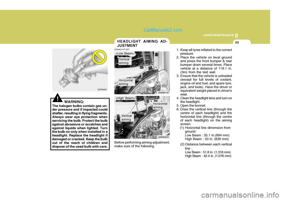
Before performing aiming adjustment, make sure of the following.HEADLIGHT AIMING AD- JUSTMENT
G290A01HP-EAT
1. Keep all tyres inflated to the correct
pressure.
2. Place the vehicle on level ground and press the front bumper & rear bumper down several times. Placevehicle at a distance of 118.1 in. (3m) from the test wall.
3. Ensure that the vehicle is unloaded (except for full levels of coolant, engine oil and fuel, and spare tyre,jack, and tools). Have the driver or equivalent weight placed in driver's seat.
4. Clean the headlight lens and turn on the headlight.
5. Open the bonnet.
6. Draw the vertical line (through the centre of each headlight) and thehorizontal line (through the centre of each headlight) on the aiming screen.
(1) Horizontal line dimension from
Horizontal aiming
Vertical aiming
G290B01HP
G290B02HP
Horizontal aiming
Vertical aiming
ground :Low Beam : 35.1 in.(894 mm) High Beam : 33 in. (839 mm)
(2) Distance between each vertical line :Low Beam : 51.8 in. (1,316 mm) High Beam : 42.4 in. (1,076 mm)
!WARNING:
The halogen bulbs contain gas un-
der pressure and if impacted could shatter, resulting in flying fragments.Always wear eye protection when servicing the bulb. Protect the bulb against abrasions or scratches andagainst liquids when lighted. Turn the bulb on only when installed in a headlight. Replace the headlight ifdamaged or cracked. Keep the bulb out of the reach of children and dispose of the used bulb with care. G270A03O