Page 273 of 539
6 DO-IT-YOURSELF MAINTENANCE
46
AMPERAGES(A)50A 30A 40A 40A 30A 40A 20A-
20A 10A 15A
NO. 1
NO. 2
NO. 3
NO. 4
NO. 5
NO. 6
NO. 7
NO. 8
NO. 9
DESCRIPTION
CIRCUIT PROTECTED
Power Connector(A,B), Engine Compartment Fuse and Relay Box #2
(Fuse 28,29), Inner Panel Fuse Box(Fuse 6,7,8, 9)
Start Relay, Ignition Switch
Condenser Fan Relay,
Engine Compartment Fuse and Relay Box #2(Fuse 14,15)ABS Control Module
Power Window Relay
Tail Lamp Relay,
Engine Compartment Fuse and Relay Box #2(Fuse 11,12)ABS Control Module-
Fuel Pump Relay, ECM, Ignition Failure Sensor
A/CON, TCM, ETACM, Data Link Connector, Siren,
Immobilizer Control Module
Interior Lamp, Map Lamp, Audio, Instrument Cluster,
Front Door Edge warning Lamp
FUSIBLE LINK
NO. 30
NO. 31
Page 274 of 539

6
DO-IT-YOURSELF MAINTENANCE
47
NO. 1 2 34 5 67 8 9
10 11 1213 14 1516 17 1819 20 2122 23 2425 26 2728 AMPERAGES(A)
30A 10A 15A 20A10A15A30A20A 10A 10A20A10A- -
10A 10A -
10A10A10A10A 10A 10A
-
10A15A15A 10A CIRCUIT PROTECTED
Defogger Relay
Hazard Relay, Hazard Switch Stop Lamp Switch
TOD, EST Control Module - Sunroof Controller
Blower Relay
Power Door Locks
Rear Fog Lamp Relay
Audio, Map Lamp
Cigarette Lighter, Power Outlet relay, ACC Socket
Power Outside Mirror Switch- - A/C Switch
Left/Right Outside Mirror & Defogger -
TCM, ECM(COVEC-F), TCCS(TOD, EST), Immobilizer
Back-up Lamp Switch, Inside Rearview Mirror, Transmission Range Switch Hazard Switch
Instrument Cluster, ETACM, Vehicle Speed Sensor, DRL Control ModuleAirbag Airbag Indicator -
Blower & A/C, ETACM, Defogger Relay
Seat Warmer
Sunroof, Rear Wiper & Washer, Cruise Switch, Rear Intermittent Wiper Relay
Start Relay, Theft-Alarm Relay
G200E01HP-GAT
Inner Panel
Note: Not all fuse panel descriptions in this manual may be applicable to your vehicle. It is accurate at the time of printing. When you inspect the fuse box on your vehicle, refer to the fuse box label. G200D01HP
Page 480 of 539
6 OWNER MAINTENANCE
2
1. Power steering fluid reservoir 2. Brake fluid reservoir 3. Engine cover 4. Battery 5. Fuse and relay box 6. Windscreen washer fluid reservoir
7. Air cleaner filter
8. Radiator cap
9. Engine oil filler cap
10. Automatic transmission fluid level
dipstick (Vehicle with automatictransmission)
11. Engine oil level dipstick
12. Coolant reservoir cap
G010A01HP-EAT Petrol Engine Compartment (3.5 V6)
CAUTION:
When inspecting or servic-
ing the engine, you should handle tools and other heavy objects carefully so that the plastic cover of theengine is not damaged.
!
ENGINE COMPARTMENT
G010A01HP-E
Page 481 of 539
6
OWNER MAINTENANCE
3
G010C01HP-EAT
Diesel Engine Compartment (2.9 CRDi)
1. Brake fluid reservoir
2. Clutch fluid reservoir (Not all models)
3. Engine oil level dipstick
4. Engine cover 5. Engine oil filler cap
6. Battery
7. Fuse and relay box
8. Windscreen washer fluid reservoir
9. Air cleaner filter10. Radiator cap
11. Fuel filter
12. Power steering fluid reservoir
13. Coolant reservoir capCAUTION:
When inspecting or servic-ing the engine, you shouldhandle tools and other heavy objects carefully so that the plastic cover of theengine is not damaged.
!
G010C01HP-E
Page 503 of 539

6
OWNER MAINTENANCE
25
!
!
1. Loosen the adusting bolts just
enough so that the components can be moved.
2. Whilst pulling outward on the pry bar
or screwdriver, test the belt deflec-tion with your thumb.
3. After tightening the adjusting bolts, be sure to recheck the belt tension. Overtightening drive belts can cause excessive wear and failurein driven components and belts.
WARNING:
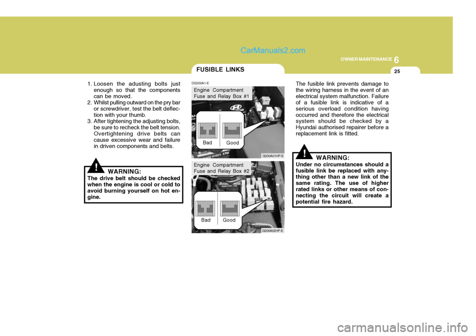
The drive belt should be checked when the engine is cool or cold to avoid burning yourself on hot en-gine. The fusible link prevents damage tothe wiring harness in the event of anelectrical system malfunction. Failure of a fusible link is indicative of a serious overload condition havingoccurred and therefore the electrical system should be checked by a Hyundai authorised repairer before areplacement link is fitted.
WARNING:
Under no circumstances should afusible link be replaced with any- thing other than a new link of the same rating. The use of higherrated links or other means of con- necting the circuit will create a potential fire hazard.
FUSIBLE LINKS
DG200A1-E
G200A01HP-E
Bad
Good
G200A02HP-E
Bad Good
Engine Compartment Fuse and Relay Box #1
Engine Compartment Fuse and Relay Box #2
Page 504 of 539

6 OWNER MAINTENANCE
26
!
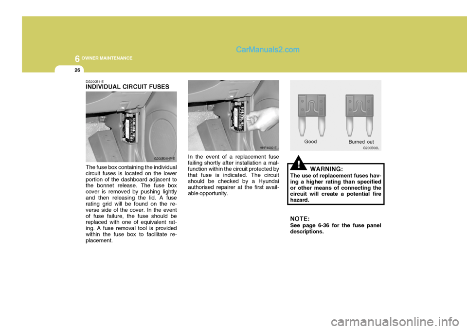
DG200B1-E INDIVIDUAL CIRCUIT FUSES The fuse box containing the individual circuit fuses is located on the lowerportion of the dashboard adjacent to the bonnet release. The fuse box cover is removed by pushing lightlyand then releasing the lid. A fuse rating grid will be found on the re- verse side of the cover. In the eventof fuse failure, the fuse should be replaced with one of equivalent rat- ing. A fuse removal tool is providedwithin the fuse box to facilitate re- placement. In the event of a replacement fuse
failing shortly after installation a mal-function within the circuit protected by that fuse is indicated. The circuitshould be checked by a Hyundai authorised repairer at the first avail- able opportunity. WARNING:
The use of replacement fuses hav-ing a higher rating than specifiedor other means of connecting the circuit will create a potential fire hazard. NOTE: See page 6-36 for the fuse panel descriptions.
G200B01HP-E
HHP4002-E
Good G200B02L
Burned out
Page 505 of 539

6
OWNER MAINTENANCE
27
!WARNING:
Motor vehicle batteries contain sulphuric acid which is corrosive and poisonous. Hydrogen gas isemitted from the battery which is explosive when combined with oxygen. The following precautionsmust be strictly observed to avoid personal injury or damage to the vehicle.
BATTERY MAINTENANCE
DG210A2-E
HHP5020-E
G200C01HP-GAT
Power connector NOTE:
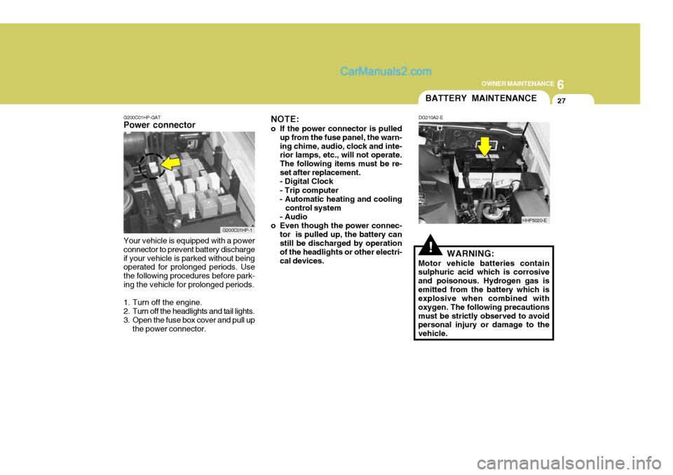
o If the power connector is pulled up from the fuse panel, the warn- ing chime, audio, clock and inte- rior lamps, etc., will not operate. The following items must be re-set after replacement.- Digital Clock - Trip computer
- Automatic heating and cooling
control system
- Audio
o Even though the power connec- tor is pulled up, the battery can still be discharged by operation of the headlights or other electri-cal devices.
Your vehicle is equipped with a powerconnector to prevent battery dischargeif your vehicle is parked without being operated for prolonged periods. Use the following procedures before park-ing the vehicle for prolonged periods.
1. Turn off the engine.
2. Turn off the headlights and tail lights.
3. Open the fuse box cover and pull up the power connector.
G200C01HP-1
Page 514 of 539
6 OWNER MAINTENANCE
36
NO.1
NO. 2
NO. 3
NO.4
NO.5
NO. 6
NO. 7
NO. 8
NO. 9
NO. 10
NO. 11
NO. 12
DESCRIPTION
G200C01HP-EAT Engine Compartment (#1)
G200C01HP-E
NOTE: Not all fuse panel descriptions in this manual may be applicable to your vehicle. It is accurate at the time of printing. When you inspect the fuse box on your vehicle, refer to the fuse box label. AMPERAGES
100A
120A (DIESEL)
140A ( PETROL)
50A 30A - -
20A 10A 15A -
10A10A CIRCUIT PROTECTED
Glow Relay (COVEC-F/EGR), Air Heater Relay (Diesel Engine) Engine Compartment Fuse & Relay Box #2,GeneratorInner Panel Fuse Box (Fuse 1,2,3,4,5),Engine Compartment Fuse & Relay Box #1 (Fuse 8,9),
Fuel Heater Control Module (COVEC-F/EGR)
Generator, Ignition Switch--Engine Control Relay (Diesel Engine),
Main Control Relay (Petrol Engine)Horn RelayFront Fog Lamp Relay-ECM (Diesel Engine), EGR Control ModuleECM (Diesel Engine)
FUSIBLE LINK
FUSE
FUSE PANEL DESCRIPTION
Petrol Engine Diesel Engine