Page 224 of 539
5
VEHICLE MAINTENANCE REQUIREMENTS
9EXPLANATION OF SCHEDULED MAINTENANCE ITEMS
!
F060M01A-AAT
o Engine Oil and Filter
The engine oil and filter should be changed at the intervals specified in the maintenance schedule. If the car is being driven in severe conditions,more frequent oil and filter changes are required. F060B01A-AAT
o Drive belts
Inspect all drive belts for evidence of cuts, cracks, excessive wear or oil saturation and replace if necessary. Drive belts should be checked periodi-cally for proper tension and adjusted as necessary. F060C01A-AAT
o Fuel filter
A clogged filter can limit the speed at
which the vehicle may be driven, dam-age the emission system and cause hard starting. If an excessive amountof foreign matter accumulates in the fuel tank, the filter may require re- placement more frequently. After installing a new filter, run the
engine for several minutes, and checkfor leaks at the connections. Fuel fil- ters should be installed by trained technicians. WARNING (Diesel only):
Never work on injection system with
engine running or within 30 sec- onds after shutting off engine. High pressure pump, rail, injectors andhigh pressure pipes are subjected to high pressure even after the en- gine has been switched off. The fueljet produced by fuel leaks may cause serious injury, if it contacts with the body. People using pacemakersshould not move closer than 30cm to the ECU or wiring harness within the engine room with the enginerunning, since the high currents in the Common Rail system produce considerable magnetic fields.
F060D01TB-GAT
o Fuel Lines, Fuel Hoses and
Connections
Check the fuel lines, fuel hoses and connections for leakage and damage. Have a trained technician replace any damaged or leaking parts immediately.
Page 247 of 539
6 DO-IT-YOURSELF MAINTENANCE
20
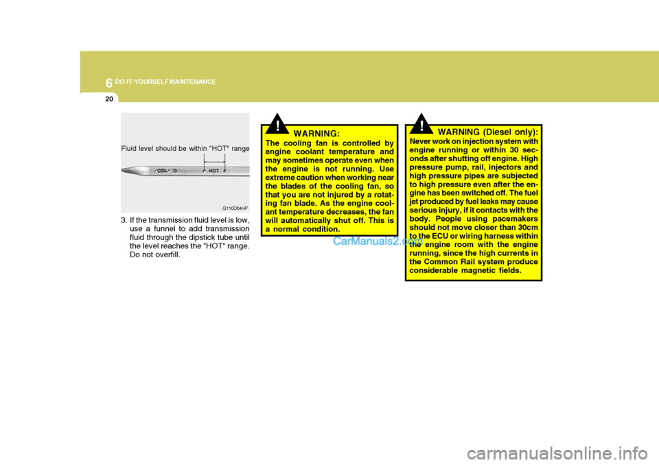
Fluid level should be within "HOT" range
3. If the transmission fluid level is low,
use a funnel to add transmission fluid through the dipstick tube until the level reaches the "HOT" range. Do not overfill. G110D04HP
!!WARNING:
The cooling fan is controlled by engine coolant temperature and may sometimes operate even whenthe engine is not running. Use extreme caution when working near the blades of the cooling fan, sothat you are not injured by a rotat- ing fan blade. As the engine cool- ant temperature decreases, the fanwill automatically shut off. This is a normal condition. WARNING (Diesel only):
Never work on injection system with
engine running or within 30 sec- onds after shutting off engine. High pressure pump, rail, injectors and high pressure pipes are subjectedto high pressure even after the en- gine has been switched off. The fuel jet produced by fuel leaks may causeserious injury, if it contacts with the body. People using pacemakers should not move closer than 30cmto the ECU or wiring harness within the engine room with the engine running, since the high currents inthe Common Rail system produce considerable magnetic fields.
Page 261 of 539

6 DO-IT-YOURSELF MAINTENANCE
34
To check the power steering fluid level, be sure the ignition is "OFF", thencheck to make certain that the power steering fluid level is between the "MAX" and "MIN" level markings onthe fluid reservoir. NOTE: Grinding noise from the power steer- ing pump may be heard immedi- ately after the engine is started inextremely cold conditions (below - 20°C). If the noise stops during warm up, there is no abnormal function inthe system. If is due to a power steering fluid characteristic in ex- tremely cold conditions. Recommended Fluid Use PSF-3 type fluid. NOTE: Do not start the engine when the power steering oil reservoir is empty.
FUEL FILTER
G240A01A-AAT
POWER STEERING HOSES
It is suggested that you check the
power steering hose connections for fluid leakage at regular intervals. The power steering hoses should be re-placed if there is severe surface crack- ing, pulling, scuffing or worn spots. Deterioration of the hose could causepremature failure. G350A02HP-GAT
Bleeding the Fuel System (For Diesel Engine (2.5 TCI))
The fuel system should be bled to
remove air as described in the illus- tration if the fuel supply is exhausted during travel, when the fuel filter isreplaced, or if the vehicle is not used for a long time.
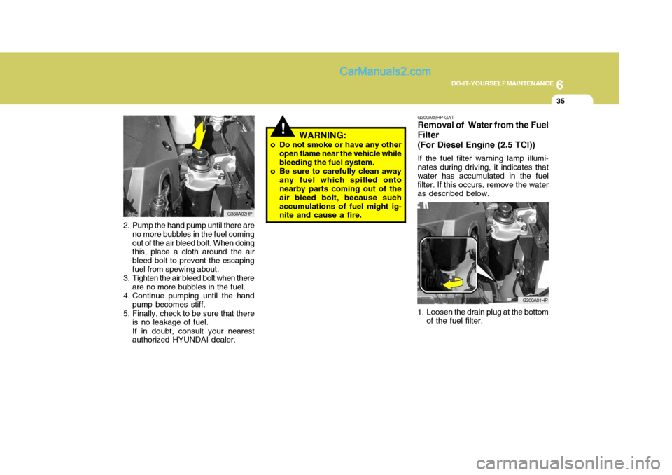
1. Loosen the air bleed bolt at the upper part of the fuel filter with a flat-head screwdriver or equivalent. G350A01HP
Page 262 of 539
6
DO-IT-YOURSELF MAINTENANCE
35
!WARNING:
o Do not smoke or have any other open flame near the vehicle while bleeding the fuel system.
o Be sure to carefully clean away any fuel which spilled onto nearby parts coming out of the air bleed bolt, because suchaccumulations of fuel might ig- nite and cause a fire. G300A02HP-GAT Removal of Water from the Fuel Filter (For Diesel Engine (2.5 TCI)) If the fuel filter warning lamp illumi- nates during driving, it indicates thatwater has accumulated in the fuel filter. If this occurs, remove the water as described below.
G300A01HP
1. Loosen the drain plug at the bottom of the fuel filter.
2. Pump the hand pump until there are
no more bubbles in the fuel comingout of the air bleed bolt. When doing this, place a cloth around the air bleed bolt to prevent the escapingfuel from spewing about.
3. Tighten the air bleed bolt when there
are no more bubbles in the fuel.
4. Continue pumping until the hand pump becomes stiff.
5. Finally, check to be sure that there is no leakage of fuel. If in doubt, consult your nearest authorized HYUNDAI dealer. G350A02HP
Page 263 of 539
6 DO-IT-YOURSELF MAINTENANCE
36
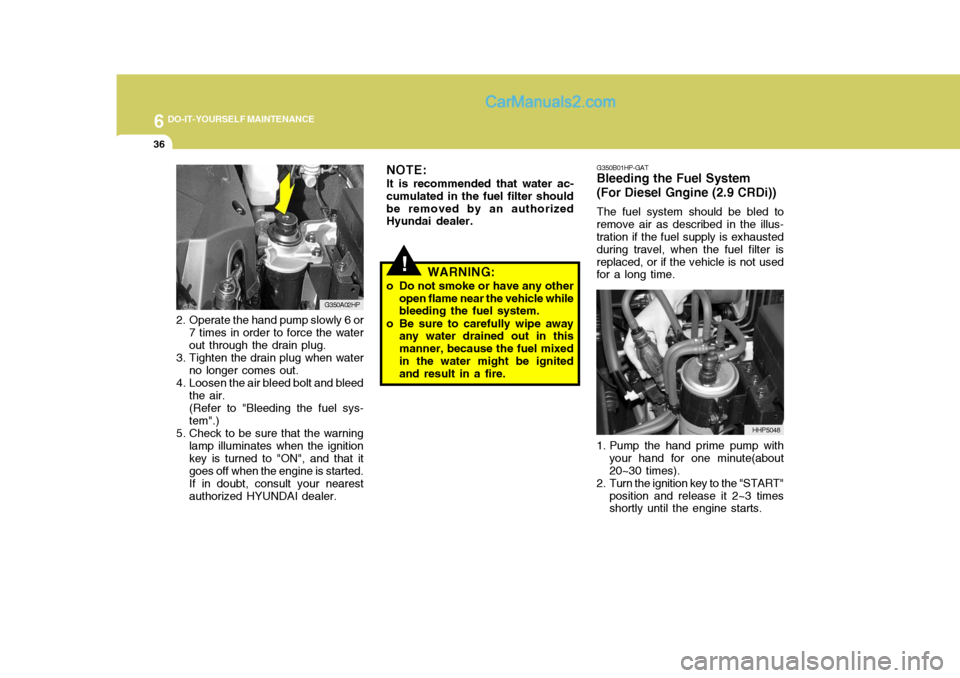
2. Operate the hand pump slowly 6 or
7 times in order to force the water out through the drain plug.
3. Tighten the drain plug when water no longer comes out.
4. Loosen the air bleed bolt and bleed the air.(Refer to "Bleeding the fuel sys-tem".)
5. Check to be sure that the warning lamp illuminates when the ignitionkey is turned to "ON", and that itgoes off when the engine is started.If in doubt, consult your nearestauthorized HYUNDAI dealer. G350A02HP
!
NOTE: It is recommended that water ac-
cumulated in the fuel filter should be removed by an authorized Hyundai dealer. G350B01HP-GAT
Bleeding the Fuel System (For Diesel Gngine (2.9 CRDi))
The fuel system should be bled to
remove air as described in the illus- tration if the fuel supply is exhausted during travel, when the fuel filter isreplaced, or if the vehicle is not used for a long time.
1. Pump the hand prime pump with your hand for one minute(about 20~30 times).
2. Turn the ignition key to the "START"
position and release it 2~3 times shortly until the engine starts. HHP5048
WARNING:
o Do not smoke or have any other open flame near the vehicle whilebleeding the fuel system.
o Be sure to carefully wipe away any water drained out in this manner, because the fuel mixedin the water might be ignited and result in a fire.
Page 264 of 539
6
DO-IT-YOURSELF MAINTENANCE
37
!
G300B02HP-GAT
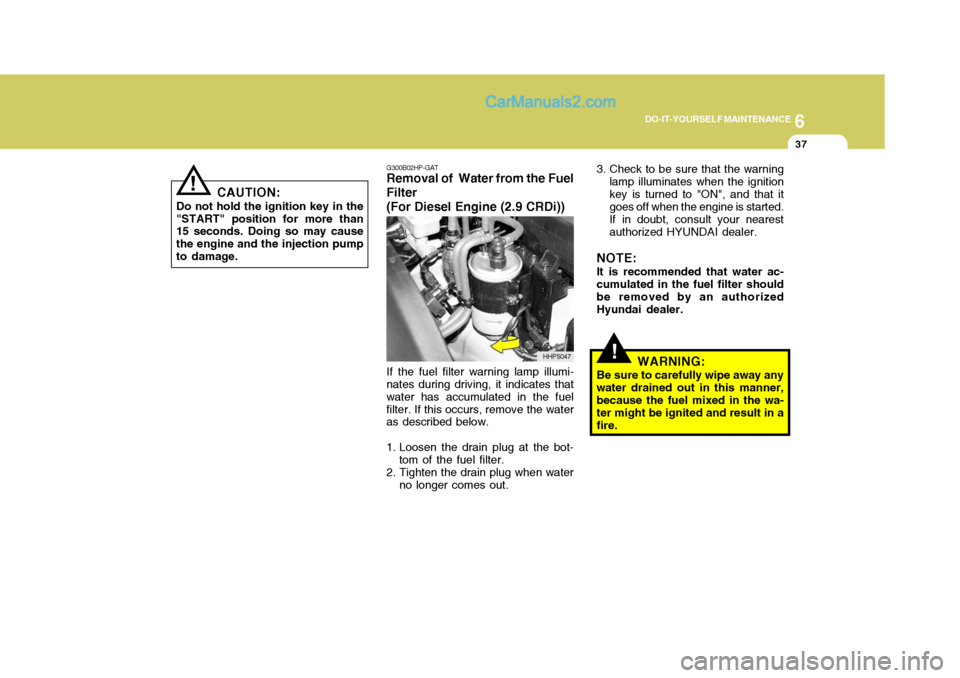
Removal of Water from the Fuel Filter (For Diesel Engine (2.9 CRDi))
If the fuel filter warning lamp illumi-
nates during driving, it indicates that water has accumulated in the fuelfilter. If this occurs, remove the water as described below.
1. Loosen the drain plug at the bot-
tom of the fuel filter.
2. Tighten the drain plug when water
no longer comes out. 3. Check to be sure that the warning
lamp illuminates when the ignition key is turned to "ON", and that it goes off when the engine is started. If in doubt, consult your nearest authorized HYUNDAI dealer.
NOTE: It is recommended that water ac- cumulated in the fuel filter should be removed by an authorizedHyundai dealer.
WARNING:
Be sure to carefully wipe away anywater drained out in this manner,because the fuel mixed in the wa- ter might be ignited and result in a fire.
HHP5047
!
CAUTION:
Do not hold the ignition key in the "START" position for more than 15 seconds. Doing so may cause the engine and the injection pumpto damage.
Page 273 of 539
6 DO-IT-YOURSELF MAINTENANCE
46
AMPERAGES(A)50A 30A 40A 40A 30A 40A 20A-
20A 10A 15A
NO. 1
NO. 2
NO. 3
NO. 4
NO. 5
NO. 6
NO. 7
NO. 8
NO. 9
DESCRIPTION
CIRCUIT PROTECTED
Power Connector(A,B), Engine Compartment Fuse and Relay Box #2
(Fuse 28,29), Inner Panel Fuse Box(Fuse 6,7,8, 9)
Start Relay, Ignition Switch
Condenser Fan Relay,
Engine Compartment Fuse and Relay Box #2(Fuse 14,15)ABS Control Module
Power Window Relay
Tail Lamp Relay,
Engine Compartment Fuse and Relay Box #2(Fuse 11,12)ABS Control Module-
Fuel Pump Relay, ECM, Ignition Failure Sensor
A/CON, TCM, ETACM, Data Link Connector, Siren,
Immobilizer Control Module
Interior Lamp, Map Lamp, Audio, Instrument Cluster,
Front Door Edge warning Lamp
FUSIBLE LINK
NO. 30
NO. 31
Page 288 of 539
9 VEHICLE SPECIFICATIONS
2
J010A02HP-GAT MEASUREMENT
4700 (4765* 1
)
1860
1795 (1840* 2
)
2750 15301530
Overall length Overall width Overall heightWheel base Wheel tread
Front
Rear
Type Wheel free play Oil pump type Ball and nut, torsion bar type (Integral type) 0 ~ 30 mm (0 ~ 1.18 in.)Vane type
J060A01Y-GAT FUEL SYSTEM
J020A01HP-GAT POWER STEERING J030A02HP-GAT TIRE
Standard Spare
J050A02HP-GAT BRAKE Dual hydraulic with brake booster Ventilated disc Disc type Disc type (with ABS)Drum type (without ABS) Cable operated on rear wheel
Type Front brake type Rear brake type Parking brake
ITEM Battery Alternator
J040A02HP-GAT ELECTRICAL
mm
Fuel tank capacity 75 liter
2.5 TCI
MF 90AH
90A (12 V)
Tire Size
255/65 R16 Full Size Kpa(psi)
2.9 CRDi
MF 100AH
110A (12V)GASOLINE
MF 68AH
120A (13.5V)DIESEL
E.C only Except E.C*1: With Bumper Guard *2: With Roof Rack Inflation Pressure
200kPa (29 psi)