Page 385 of 539
1
CONTROLS AND EQUIPMENT
77
!
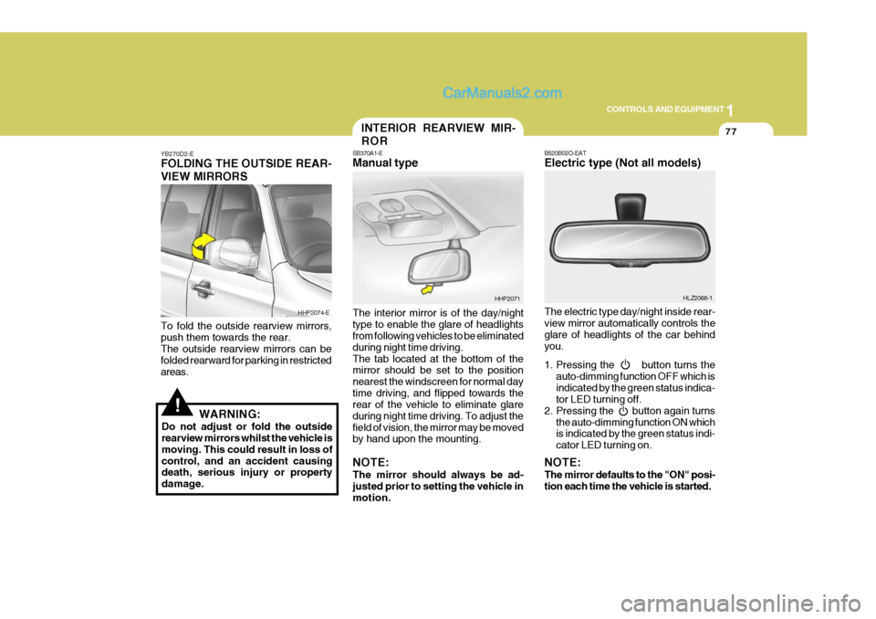
YB270D2-E FOLDING THE OUTSIDE REAR- VIEW MIRRORS To fold the outside rearview mirrors, push them towards the rear. The outside rearview mirrors can be folded rearward for parking in restrictedareas.
WARNING:
Do not adjust or fold the outside rearview mirrors whilst the vehicle is moving. This could result in loss ofcontrol, and an accident causing death, serious injury or property damage. The interior mirror is of the day/nighttype to enable the glare of headlights from following vehicles to be eliminated during night time driving.The tab located at the bottom of the mirror should be set to the position nearest the windscreen for normal daytime driving, and flipped towards the rear of the vehicle to eliminate glare during night time driving. To adjust thefield of vision, the mirror may be moved by hand upon the mounting. NOTE: The mirror should always be ad- justed prior to setting the vehicle in motion.
HHP2074-E
HHP2071
INTERIOR REARVIEW MIR- ROR
SB370A1-E Manual type
B520B02O-EAT Electric type (Not all models) The electric type day/night inside rear- view mirror automatically controls the glare of headlights of the car behindyou.
1. Pressing the button turns the
auto-dimming function OFF which is indicated by the green status indica- tor LED turning off.
2. Pressing the button again turns the auto-dimming function ON whichis indicated by the green status indi- cator LED turning on.
NOTE: The mirror defaults to the "ON" posi- tion each time the vehicle is started. HLZ2068-1
Page 386 of 539
1CONTROLS AND EQUIPMENT
78
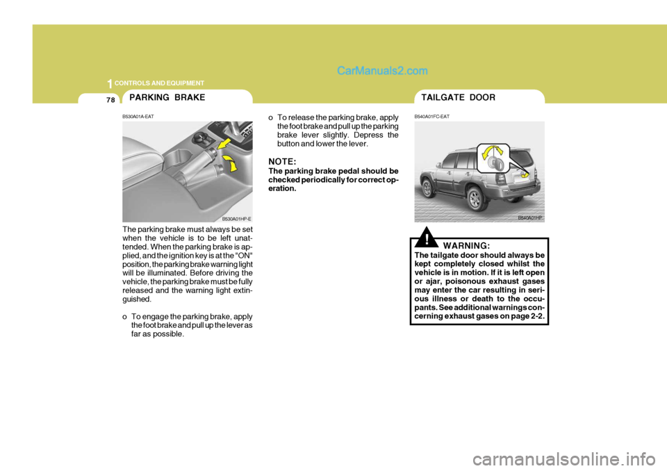
o To release the parking brake, applythe foot brake and pull up the parking brake lever slightly. Depress the button and lower the lever.
NOTE: The parking brake pedal should be checked periodically for correct op- eration.
The parking brake must always be set when the vehicle is to be left unat- tended. When the parking brake is ap- plied, and the ignition key is at the "ON"position, the parking brake warning light will be illuminated. Before driving the vehicle, the parking brake must be fullyreleased and the warning light extin- guished.
o To engage the parking brake, apply the foot brake and pull up the lever as far as possible.PARKING BRAKE
B530A01A-EAT
B530A01HP-E
!
B540A01HP
TAILGATE DOOR
B540A01FC-EAT
WARNING:
The tailgate door should always be
kept completely closed whilst the vehicle is in motion. If it is left openor ajar, poisonous exhaust gases may enter the car resulting in seri- ous illness or death to the occu-pants. See additional warnings con- cerning exhaust gases on page 2-2.
Page 387 of 539
1
CONTROLS AND EQUIPMENT
79
o The tailgate door can be locked or unlocked with a key.
o The tailgate door is opened by pulling the outside handle up, raising the tailgate door manually.
o To close, lower the tailgate door, then press down on it until it isclosed. To be sure the tailgate dooris fully closed, always try to pull it up again without using the outside handle.
!
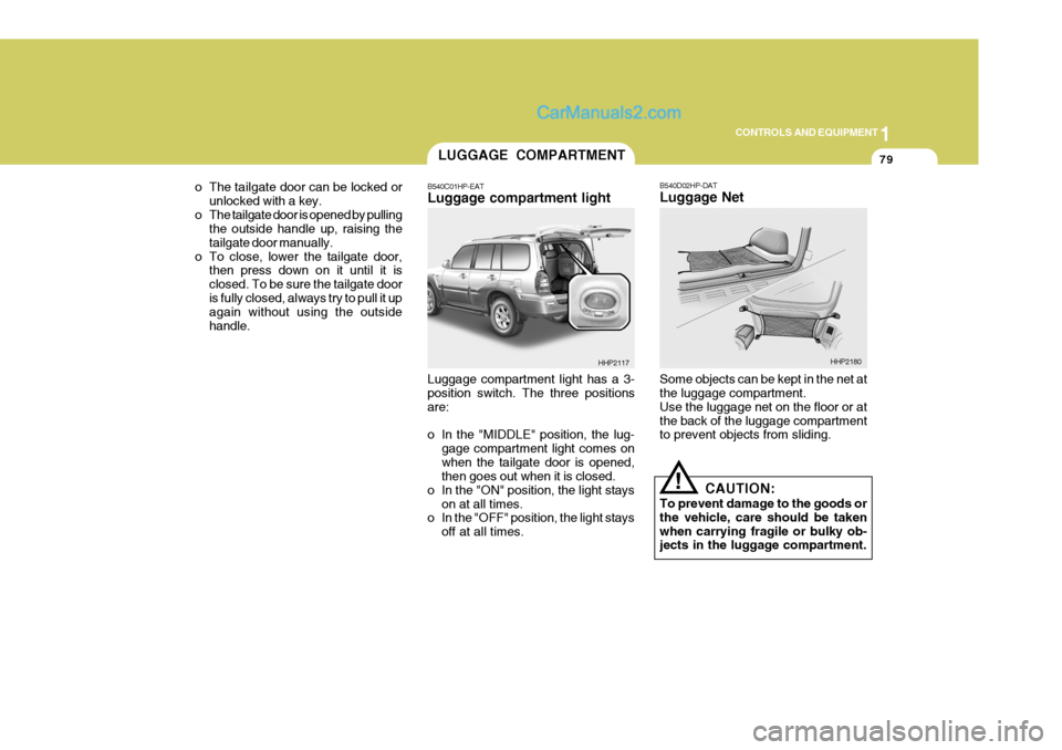
Luggage compartment light has a 3- position switch. The three positions are:
o In the "MIDDLE" position, the lug-
gage compartment light comes on when the tailgate door is opened, then goes out when it is closed.
o In the "ON" position, the light stays on at all times.
o In the "OFF" position, the light stays
off at all times. B540D02HP-DAT Luggage Net Some objects can be kept in the net at the luggage compartment. Use the luggage net on the floor or atthe back of the luggage compartment to prevent objects from sliding.
CAUTION:
To prevent damage to the goods or the vehicle, care should be takenwhen carrying fragile or bulky ob- jects in the luggage compartment.
LUGGAGE COMPARTMENT
B540C01HP-EAT Luggage compartment light
HHP2117HHP2180
Page 390 of 539

1CONTROLS AND EQUIPMENT
82
!The fuel-filler flap may be opened from inside the vehicle by pulling up on the fuel-filler flap opener located below the left of the driver's side crash pad. NOTE: If the fuel-filler flap will not open because ice has formed around it,lightly tap or push on the lid to break the ice and release it. Do not lever the flap. If necessary, spray around theflap with an approved de-icer fluid (do not use radiator anti-freeze) or move the vehicle to a warmer areaplace and allow the ice to melt. WARNING:
o Fuel vapors are dangerous. Be- fore refueling, always stop the engine and never allow sparks or open flames near the filler area. Ifyou need to replace the filler cap, use a genuine Hyundai replace- ment part.If you open the fuel filler cap dur- ing high ambient temperatures, a slight "pressure sound" may beheard. This is normal and not a cause for concern. Whenever you open the fuel fillercap, turn it slowly.
REMOTE FUEL-FILLER FLAP RELEASE
HPB360A2-E
B560A01HP-EHHP2015-D
In addition to the lower-mounted rear stop lights on either side of the car, the high mounted rear stop light in the centre of the rear window also lightswhen the brakes are applied.
HIGH-MOUNTED REAR STOP LIGHT
B550A01A-EAT
B550A01HP
Page 391 of 539
1
CONTROLS AND EQUIPMENT
83
o Automotive fuels are flammable/ explosive materials. When refuel- ing, please note the followingguidelines carefully. Failure to follow these guidelines may re- sult in severe personal injury, se-vere burns or death by fire or explosion.
- Before refueling always note the
location of the Emergency Fuel Shut-Off, if available, at the fuel station facility.
- Before touching the fuel nozzle or fuel filler cap, you shouldeliminate potentially dangerousstatic electricity discharge by touching another metal part of the front of the vehicle, a safedistance away from the fuel filler neck, nozzle, or other fuel source.
- Do not get back into a vehicle once you have begun refueling.Do not touch, rub or slide againstany item or fabric (polyester, satin, nylon, etc.) capable of pro- ducing static electricity. Staticelectricity discharge can ignite fuel vapors resulting in explo sion.If you must re-enter the vehicle, you should once again elimi-nate potentially dangerous static electricity discharge by touch- ing a metal part of the vehicle,away from the fuel filler neck, nozzle or other fuel source.
- When using a portable fuel con- tainer be sure to place the con-tainer on the ground prior to refueling. Static electricity dis-charge from the container can ignite fuel vapors causing a fire. Once refueling has begun, con-tact with the vehicle should be maintained until the filling is complete. Use only portable fuelcontainers designed to carry and store fuel.
- Do not use cellular phones
around a fuel station or whilstrefueling any vehicle. Electric current and/or electronic inter-ference from cellular phones can potentially ignite fuel vapors causing a fire. If you must useyour cellular phone use it in a place away from the fuel station.
- When refueling always shut theengine off. Sparks produced by electrical components related to the engine can ignite fuel va- pors causing a fire. Always in-sure that the engine is OFF be- fore and during refueling. Once refueling is complete, check tomake sure the fuel filler cap and door are securely closed, before starting the engine.
- Do not light any fire around a fuel station. DO NOT use matchesor a lighter and DO NOT SMOKEor leave a lit cigarette in your vehicle whilst at a gas station especially during refueling.Automotive fuel is highly flam- mable and can, when ignited, result in explosion by flames.
- If a fire breaks out during refuel- ing, leave the vicinity of the ve-hicle, and immediately contactthe manager of the fuel station or contact the police and local fire department. Follow anysafety instructions they provide.
Page 393 of 539
1
CONTROLS AND EQUIPMENT
85
A red light comes on when the front door is opened. The purpose of this light is to assist when you get in or out and also to warn passing vehicles.FRONT DOOR EDGE WARNING LIGHT
B620A01S-EAT
B620A01HP-E
!
NOTE: The Supplemental Restraint System (SRS) label containing useful infor- mation can be found in the front ofeach sun visor.
WARNING:
Do not place the sun visor in such amanner that it obscures visibility ofthe roadway, traffic or other objects.
Press the pad on the steering wheel tosound the horn.
HHP2070
HORN
B610A01L-GAT
Page 394 of 539
1CONTROLS AND EQUIPMENT
86
!
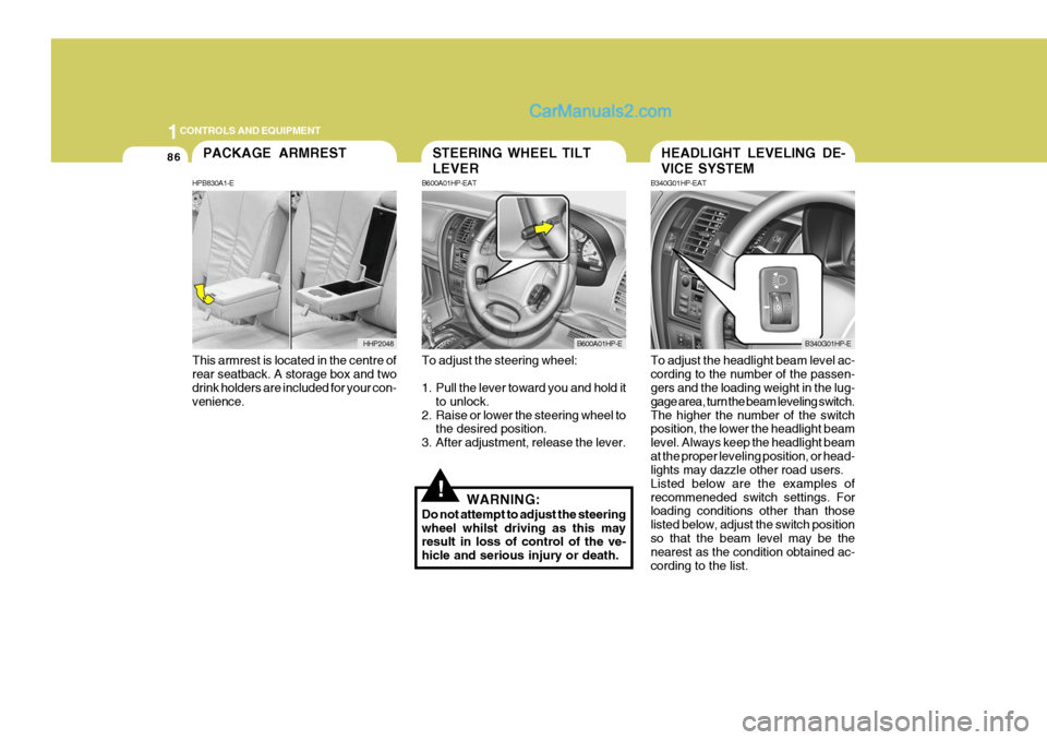
To adjust the steering wheel:
1. Pull the lever toward you and hold it
to unlock.
2. Raise or lower the steering wheel to the desired position.
3. After adjustment, release the lever.
WARNING:
Do not attempt to adjust the steering wheel whilst driving as this may result in loss of control of the ve- hicle and serious injury or death. To adjust the headlight beam level ac-cording to the number of the passen- gers and the loading weight in the lug- gage area, turn the beam leveling switch.The higher the number of the switch position, the lower the headlight beam level. Always keep the headlight beamat the proper leveling position, or head- lights may dazzle other road users. Listed below are the examples ofrecommeneded switch settings. For loading conditions other than those listed below, adjust the switch positionso that the beam level may be the nearest as the condition obtained ac- cording to the list.
STEERING WHEEL TILT LEVER
B600A01HP-EAT
B600A01HP-E
HEADLIGHT LEVELING DE- VICE SYSTEM
B340G01HP-EAT
B340G01HP-E
This armrest is located in the centre of rear seatback. A storage box and two drink holders are included for your con- venience.
PACKAGE ARMREST
HPB830A1-E
HHP2048
Page 395 of 539
1
CONTROLS AND EQUIPMENT
87
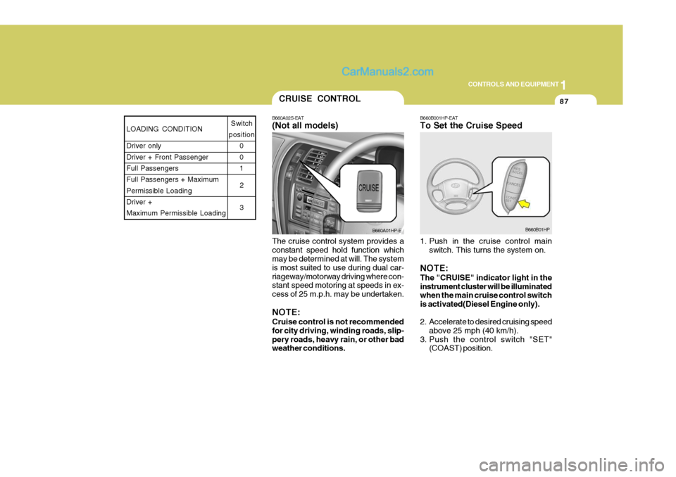
The cruise control system provides a constant speed hold function which may be determined at will. The system is most suited to use during dual car-riageway/motorway driving where con- stant speed motoring at speeds in ex- cess of 25 m.p.h. may be undertaken. NOTE: Cruise control is not recommended for city driving, winding roads, slip-pery roads, heavy rain, or other bad weather conditions.CRUISE CONTROL
B660A02S-EAT (Not all models)
B660A01HP-E
LOADING CONDITION Driver only Driver + Front PassengerFull Passengers Full Passengers + Maximum Permissible LoadingDriver + Maximum Permissible Loading Switch
position 0 01
2 3
B660B001HP-EAT To Set the Cruise Speed
1. Push in the cruise control main switch. This turns the system on.
NOTE: The "CRUISE" indicator light in the instrument cluster will be illuminated when the main cruise control switch is activated(Diesel Engine only).
2. Accelerate to desired cruising speed above 25 mph (40 km/h).
3. Push the control switch "SET" (COAST) position.
B660B01HP