Page 335 of 490

1
CONTROLS AND EQUIPMENT
55
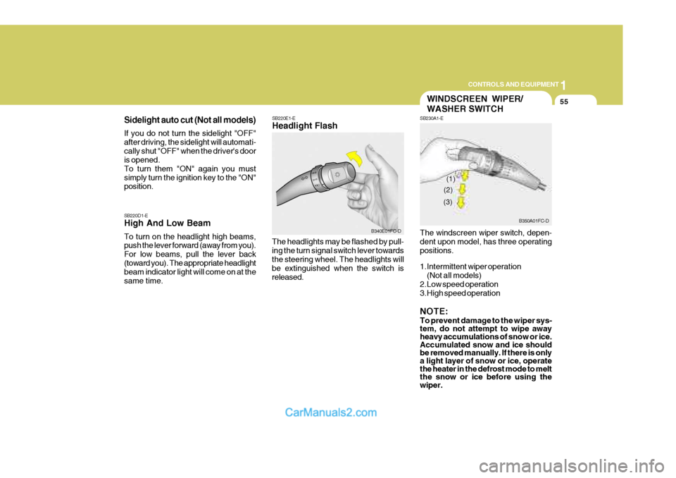
Sidelight auto cut (Not all models) If you do not turn the sidelight "OFF" after driving, the sidelight will automati-cally shut "OFF" when the driver's door is opened. To turn them "ON" again you mustsimply turn the ignition key to the "ON" position. SB220E1-E Headlight Flash
The headlights may be flashed by pull- ing the turn signal switch lever towards the steering wheel. The headlights will be extinguished when the switch isreleased.
SB220D1-E High And Low Beam To turn on the headlight high beams, push the lever forward (away from you). For low beams, pull the lever back(toward you). The appropriate headlight beam indicator light will come on at the same time.
B340E01FC-D
WINDSCREEN WIPER/ WASHER SWITCH
SB230A1-E The windscreen wiper switch, depen- dent upon model, has three operating positions.
1.Intermittent wiper operation
(Not all models)
2.Low speed operation
3.High speed operation NOTE: To prevent damage to the wiper sys- tem, do not attempt to wipe away heavy accumulations of snow or ice. Accumulated snow and ice should be removed manually. If there is onlya light layer of snow or ice, operate the heater in the defrost mode to melt the snow or ice before using the wiper.
B350A01FC-D
(1)
(2)
(3)
Page 349 of 490

1
CONTROLS AND EQUIPMENT
69SUN VISOR
SB370A1-E INTERIOR REAR VIEW MIRROR The interior mirror is of the day/night type to enable the glare of headlights from following vehicles to be eliminated during night time driving.The tab located at the bottom of the mirror should be set to the position nearest the windscreen for normal daytime driving, and flipped towards the rear of the vehicle to eliminate glare during night time driving. To adjust thefield of vision, the mirror may be moved by hand upon the mounting. NOTE: The mirror should always be ad- justed prior to setting the vehicle in motion. HXDFL2112
!
NOTE: The Supplemental Restraint System (SRS) label containing useful infor- mation can be found on the back ofeach sun visor.
WARNING:
Do not place the sun visor in such amanner that it obscures visibility of the roadway, traffic or other objects.
B580A01E-EAT
Sun visors are fitted to both the driverand passenger side of the vehicle. Cer- tain derivatives are equipped with avanity mirror which is located on the back of the driver and passenger visor. The visor may be lowered to reduce theamount of glare from directly ahead, or may be moved towards the side window to reduce glare from the side of thevehicle, once the inner pivot has been unclipped from the bracket.
HFC2094-D
Vanity mirror
Page 464 of 490

6
OWNER MAINTENANCE
35
G290A01FC
5. Open the bonnet.
6. Draw the vertical line (through the centre of each headlight beam pat- tern) and the horizontal line (through the centre of each headlight beampattern) on the aiming screen.And then, draw the horizontal paral-lel line at 1.18 in. (30 mm) under the horizontal line.
7. Adjust each cut-off line of the low beam to the parallel line with a phillipsscrewdriver - VERTICAL AIMING
8. Adjust each cut-off line of the low beam to each vertical line with a phillips screwdriver - HORIZONTALAIMING.
Horizontal Aiming
Vertical Aiming
Specifications: "H" Horizontal centre line of headlights from ground. : 26.5 in.(675 mm) "W" Distance between each headlight cen-tre. : 46.3 in. (1,177 mm) "L" Distance between the headlights andthe wall that the lights are tested against. : 118 in. (3,000 mm).
G290B02FC-EAT
Adjustment After Headlight As- sembly Replacement
If the vehicle has had front body repair
and the headlight assembly has been replaced, the headlight aiming should be checked using the aiming screenas shown in the illustration. Turn on the headlight switch. (Low Beam Posi- tion)
1. Adjust headlights so that main axis of light is parallel to the centre line of the body and is aligned with point "P" shown in the illustration.
2. Dotted lines in the illustration show the centre of the headlights. G290B01L-D
L
W
H
H Cut-off line
"P"
30mm (1.18 in.)
Vertical lineHorizontal line
Ground line