2006 Hyundai Getz fuse
[x] Cancel search: fusePage 294 of 455

FEATURES OF YOUR HYUNDAI 1- 37
B990A01TB-EAT Passenger's Front Airbag Deac- tivation/Reactivation System
B990A01TB-D
WARNING:
When the Passenger Front Air Bag system is not deactivated – Do not install a child restraint system in the front passenger seat position. Theinfant or child could be severely injured or killed by the air bag de- ploying in case of an accident.
!!
! CAUTION:
When installing a container of liquid air freshener inside a vehicle, do notplace it near the instrument cluster not on the instrument panel pad surface. If there is any leakage fromthe air freshener onto these areas (instrument cluster, instrument panel pad or air ventilator), it may damagethese parts. If the liquid from the air freshener does leak onto these ar- eas, wash them with water immedi-ately.
WARNING:
o When the SRS is activated, there may be a loud noise and fine dustwill be released throughout thevehicle. These conditions are nor- mal and are not hazardous. How- ever, the fine dust generated dur-ing airbag deployment may cause skin irritation. Be sure to wash your hands and face thoroughlywith lukewarm water and a mild soap after an accident in which the airbags were deployed. o The SRS can function only when
the ignition key is in the "ON"position. If the SRS SRI does not come on, or continuously remains on, after flashing for approimately6 seconds when the ignition key is turned to the "ON" position, or after the engine is started, or comeson while driving, the SRS is not working properly. If this occurs, have your vehicle immediatelyinspected by your Hyundai dealer.
o Before you replace a fuse or dis-
connect a battery terminal, turn the ignition key to the "LOCK" position or remove the ignitionkey. Never remove or replace the air bag related fuse(s) when the ignition key is in the "ON" posi-tion. Failure to heed this warning will cause the SRS SRI to illumi- nate.
tbuk-1a.p65 3/6/2007, 10:22 AM
37
Page 314 of 455

FEATURES OF YOUR HYUNDAI 1- 57
SB220A1-E MULTI FUNCTION SWITCH Turn Signal Operation To signal an intention to turn right, the switch lever should be pressed down. To signal an intention to turn left, theswitch lever should be pushed upwards. In both instances, the turn signal lights and the instrument cluster warning lightwill flash. Upon completion of the ma- noeuvre, the lever will, under normal circumstances, return to the "Off" posi-tion. However, if the manoeuvre in- volved only a small movement of the steering wheel, the signal may need tobe cancelled manually. If either turn signal indicator flashes more rapidly than normal or refuses to flash at all, amalfunction of the turn signal system may exist. SB220B1-E Lane Change Signal To indicate an intention to change lanes, moving the lever slightly towards the direction of the relevant turn signal willcause the turn signal lights to flash. When the lever is released, it will return to the "off" position.
HTB018-D
B400B04TB-E
4. Drive Distance
o This mode indicates the drive dis-
tance travelled since the last drive time reset.
o Pressing the trip computer switch for more than 1 second, when thedrive distance is being displayed,clears the drive distance to zero.
tbuk-1a.p65 3/6/2007, 10:22 AM
57
Page 376 of 455

3- 2 WHAT TO DO IN AN EMERGENCY
HTB165
SD020B1-E IF THE ENGINE CANNOT BE CRANKED
1. If the vehicle is fitted with manual
transaxle, ensure that the clutch pedal is depressed whilst cranking the engine. If the vehicle is fitted with automatic transaxle, ensurethat the transaxle selector is at the "P" or"N" position.
2. Check the battery terminals and
connections to ensure that theseare clean and also tight.
3. If the ignition warning lights dim
when the engine is cranked and thebattery terminals have been checked, a discharged battery isindicated. SD020C1-F If Engine Turns Over Normally but Does Not Start
SD020A1-E IF THE ENGINE WILL NOT START Seek assistance from the nearest Hyundai authorised repairer with re- gard to the method of ignition and fuelsystem diagnosis.
!
HTB221
CAUTION:
If the engine refuses to start, no attempt should be made to push or tow start the vehicle. Vehicles withautomatic transaxle or fuel injec- tion will not be able to be started in this manner since no drive is trans-mitted through the automatic transaxle whilst the engine is not running, and in the case of fuelinjected derivatives, the fuel pump will not operate under tow start conditions. In addition, if the ve-hicle is equipped with an exhaust catalyst, damage to the catalyst may result if the vehicle is tow started. 4. Do not attempt to push or tow start
the vehicle, refer to "Jump Starting"for information regarding enginestarting when the battery is dis- charged.
1. Check fuel Level
2. Check all connectors at ignition coil and spark plugs. Replace any that may be discon- nected or loose.
3. Check fuel line in the engine com- partment.
4. If engine still refuses to start, call a
Hyundai authorised repairer or seek other qualified assistance.
tbuk-3.p65 3/6/2007, 10:24 AM
2
Page 404 of 455

6. Do-It-Yourself Maintenance
Engine compartment ........................................................................ 6-2
Daily operating checks ..................................................................... 6-5
Engine oil .......................................................................................... 6-6
Engine oil replenishment .................................................................. 6-8
Engine coolant Checking ................................................................. 6-9Changing the air cleaner filter ......................................................... 6-11
Windscreen Wiper Blades .............................................................. 6-12
Windscreen Washer Reservoir Replenishment ............................. 6-13
Manual Transaxle Lubricant........................................................... 6-14
Automatic Transaxle fluid ............................................................... 6-15
Brake System Checking ................................................................ 6-17
Air conditioning System .................................................................. 6-18
Drive belts ...................................................................................... 6-20
Individual Circuit Fuses .................................................................. 6-21
Power steering fluid level ............................................................... 6-23
Replacing Light Bulbs .................................................................... 6-25
Fuse panel description ................................................................... 6-31
6
tbuk-6.p65 3/6/2007, 10:26 AM
1
Page 424 of 455

DO-IT-YOURSELF MAINTENANCE 6- 21
G190B01TB-GAT CHECKING DRIVE BELTS (Diesel) At the scheduled maintenance inspec- tion, belts should be examined forcracks, wear, fraying or other evidence of deterioration and replaced if neces- sary.Belt routing should also be checked to be sure there is no interference be- tween the belts and other parts of theengine.
!
SG200A1-E FUSIBLE LINKS The fusible link prevents damage to the wiring harness in the event of an elec-trical system malfunction. Failure of a fusiblelink is indicative of a serious overload condition having occurred andtherefore the electrical system should be checked by a Hyundai authorised repairer before a replacement link isfitted.
WARNING:
Under no circumstances should afusible link be replaced with any- thing other than a new link of the same rating. The use of higher ratedlinks or other means of connecting the circuit will create a potential fire hazard.G200B01E-EAT INDIVIDUAL CIRCUIT FUSES The fuse box containing the individual circuit fuses will be found in the back-side of multi box located in the right side of driver. The multi box is removed by pulling lightly and then releasing the lid.A fuse rating grid will be found on the reverse side of the cover. In the event of fuse failure, the fuse should be re-placed with one of equivalent rating. A fuse removal tool is provided within the fuse box to facilitate replacement. HTB180-D
A/C comp.
Water pump pulley
G190B01TB
Alternator Power steering pump
Tensioner
Crankshaft pulley
tbuk-6.p65
3/6/2007, 10:27 AM
21
Page 425 of 455

6- 22 DO-IT-YOURSELF MAINTENANCE
!
o If battery electrolyte is spilled onto
skin or into eyes, the effected area must be flushed with copiousamounts of water and medical assis- tance sought.
o If battery electrolyte is ingested, copious amounts of water or milkfollowed by an ant-acid (raw egg or milk of magnesia) must be drunk.Vomiting should not be induced and medical assistance must be sought.
o Batteries must only be charged in well venti-lated areas from whichnaked lights or sources of sparks are excluded.
o Ensure that children, pets or other unauthorised persons are kept awayfrom batteries.
o Do not allow anything to bridge the positive (+) and negative (-) termi-nals of the battery.
o Never invert the battery. The battery fitted during production is of the "Maintenance Free" type.
SG210A1-E BATTERY MAINTENANCE
WARNING:
Motor vehicle batteries contain sulphuric acid which is corrosive and poisonous. Hydrogen gas isemitted from the battery which is explosive when combined with oxy- gen. The following precautions mustbe strictly observed to avoid per- sonal injury or damage to the ve- hicle.
HTB165
!
HTB223
WARNING:
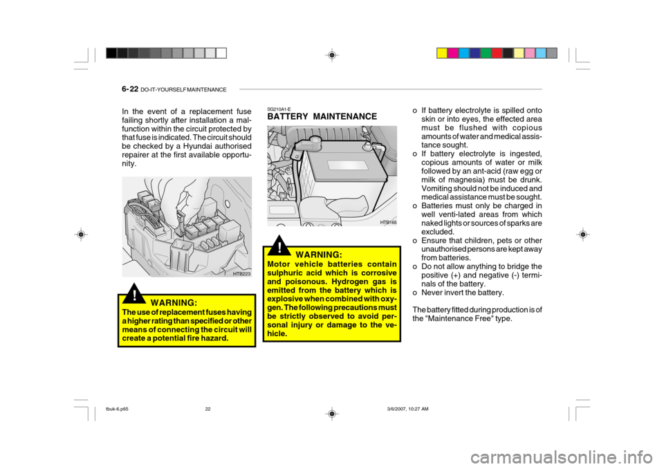
The use of replacement fuses having a higher rating than specified or othermeans of connecting the circuit will create a potential fire hazard.
In the event of a replacement fuse failing shortly after installation a mal-function within the circuit protected by that fuse is indicated. The circuit should be checked by a Hyundai authorisedrepairer at the first available opportu- nity.
tbuk-6.p65
3/6/2007, 10:27 AM
22
Page 434 of 455

DO-IT-YOURSELF MAINTENANCE 6- 31
G200C02TB-GAT FUSE PANEL DESCRIPTION Engine Compartment
PROTECTED COMPONENTS
Ignition Switch Ignition Switch, Start Relay
Fuel pump, Alternator, ECM
Radiator FanHeadlight, Defogger RelayABSC/lighterAuto Fuel Cut Switch ABS ABS
Blower, Blower Motor
Power WindowElectronic power steeringECMECMA/CON, Fuel PumpInjectorA/ConditionerHornAlternator
FUSE RATING
30A30A30A30A50A10A25A15A10A20A40A30A30A50A10A20A10A15A10A10A
100A
DESCRIPTION
IGN 2IGN 1ECURAD
BATT ABS
C/LIGHTER F/PUMPECU-BABS1ABS2BLW
P/WDW EPS
ECU-1ECU-2 SNSR INJ
A/CON HORN BATT
Note: Not all fuse panel descriptions in this manual may be applicable to your vehicle. It is accurate at the time of printing. When you inspect the fuse box on your vehicle, refer to the fuse box label.
Gasoline Engine
G200C01TB
tbuk-6.p65 3/6/2007, 10:27 AM
31
Page 435 of 455

6- 32 DO-IT-YOURSELF MAINTENANCE
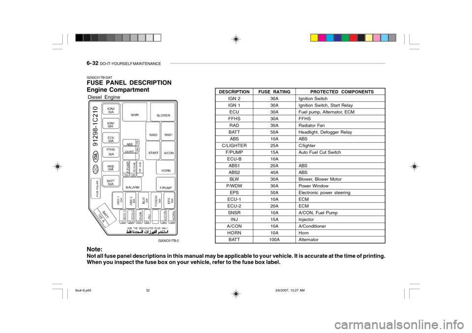
G250C01TB-GAT FUSE PANEL DESCRIPTION Engine Compartment
PROTECTED COMPONENTS
Ignition Switch Ignition Switch, Start Relay
Fuel pump, Alternator, ECMFFHS
Radiator FanHeadlight, Defogger RelayABSC/lighterAuto Fuel Cut Switch ABS ABS
Blower, Blower Motor
Power WindowElectronic power steeringECMECMA/CON, Fuel PumpInjectorA/ConditionerHornAlternator
FUSE RATING
30A30A30A30A30A50A10A25A15A10A20A40A30A30A50A10A20A10A15A10A10A
100A
DESCRIPTION
IGN 2IGN 1ECU
FFHS RAD
BATT ABS
C/LIGHTER F/PUMPECU-BABS1ABS2BLW
P/WDW EPS
ECU-1ECU-2 SNSR INJ
A/CON HORN BATT
Note: Not all fuse panel descriptions in this manual may be applicable to your vehicle. It is accurate at the time of printing. When you inspect the fuse box on your vehicle, refer to the fuse box label.
Diesel Engine
G200C01TB-2
tbuk-6.p65 3/6/2007, 10:27 AM
32