Page 229 of 319

�Ì�Ì
�µ
�Ì
Maintenance
Minder
227
:
If the message ‘‘SERVICE OIL’’ does not appear more than 12 months after
the display is reset, change the engine oil every year.
See information on maintenance and emissions warranty on page .
Independent of the maintenance minder display, replace the brake fluid
every 3 years.
Inspect idle speed every 160,000 miles (256,000 km).
Adjust the valves during services A, B, 1, 2, or 3 only if they are noisy.
NOTE: 1:
226
Maintenance Main Items
Replace engine oil
Replace engine oil and oil filter
Inspect front and rear brakes
Check parking brake adjustment
Inspect these items: Tie-rod ends, steering gear box, and boots
Suspension components
Driveshaft boots
Brake hoses and line (including ABS)
All fluid levels and condition of fluids
Exhaust system
Fuel lines and connections Maintenance Sub Items
Rotate tires
Replace air cleaner element If you drive in dusty conditions, replace
every 15,000 miles (24,000 km).
Replace dust and pollen filter If you drive primarily in urban areas that have high
concentrations of soot in the air from industry and
from diesel-powered vehicles, replace every
15,000 miles (24,000 km).
Inspect drive belt
Replace transmission fluid Driving in mountainous areas at very low vehicle
speeds or trailer towing results in higher
transmission and transfer temperatures. This
requires transmission and transfer fluid changes
more frequently than recommended by the
maintenance minder. If you regularly drive your
vehicle under these conditions, have the
transmission and transfer fluid changed at
60,000 miles (100,000 km), then every 30,000 miles
(48,000 km). (For A/T only:)
Replace spark plugs
Replace timing belt and inspect water pump
(V6 engine only) If you drive regularly in very high temperatures
(over 110°F, 43°C), in very low temperatures
(under 110°F, 29°C), replace every 60,000 mile
(U.S.)/100,000 km (Canada).
Inspect valve clearance
Replace engine coolant
A
B
Symbol
Symbol
1
2
3
4
51
1
Maintenance Minder
�����—�����—�����y�
�������������y���
�(���%�������y���������y
Page 255 of 319
To replace a wiper blade:Raise the wiper arm of f the
windshield. Raise the driver’s side
first, then the passenger’s side. Disconnect the blade assembly
fromthewiperarmbypushingin
the lock tab. Hold the lock tab in
while you push the blade assembly
toward the base of the arm.Remove the blade f rom its holder
by grasping the tabbed end of the
blade. Pull f irmly until the tabs
come out of the holder.
2.
1. 3.
CONT INUED
Wiper Blades
Maint enance
253
WIPER ARMS
LOCK TABBLADE
Do not open the hood when the wiper
arms are raised, or you will damage the
hood and the wiper arms.
�����—�����—�����y�
�������������y���
�(���%�������y���������y
Page 256 of 319

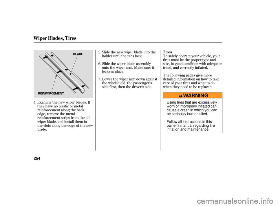
Examine the new wiper blades. If
they have no plastic or metal
reinf orcement along the back
edge, remove the metal
reinf orcement strips f rom the old
wiper blade, and install them in
the slots along the edge of the new
blade.Slide the new wiper blade into the
holder until the tabs lock.
Slide the wiper blade assembly
onto the wiper arm. Make sure it
locks in place.
Lower the wiper arm down against
the windshield, the passenger’s
side first, then the driver’s side.
To saf ely operate your vehicle, your
tires must be the proper type and
size, in good condition with adequate
tread, and correctly inf lated.
The f ollowing pages give more
detailed inf ormation on how to take
care of your tires and what to do
when they need to be replaced.
4. 5.
6.
7.
Wiper Blades, Tires
Tires
254
BLADE
REINFORCEMENT
Using tires that are excessively
worn or improperly inflated can
cause a crash in which you can
be seriously hurt or killed.
Follow all instructions in this
owner’s manual regarding tire
inflation and maintenance.
�����—�����—�����y�
���������
���y���
�(���%�������y���������y
Page 260 of 319

Replace your tires with radial tires of
the same size, load range, speed
rating, and maximum cold ti re
pressure rating (as shown on the
ti re’s sidewall).
Mixing radial and bias-ply tires on
your vehicle can reduce braking
ability, traction, and steering
accuracy. Using tires of a different
size or construction can c ause the
ABS and vehicle stability assi st
system (VSA) to work inconsistently.
TheABSworksbycomparingthe
speed of the wheels. When replac ing
tires, use the same size originally
supplied with the vehicle. Tire size
and construction can affect wheel
speed and may cause the system to
activate. It is best to replace all four ti
res at
thesametime.Ifthatisnotpossible
or necessary, replace the two front
tires or two rear tires as a pair.
Replacing just one ti re can seriously
affect your vehicl e’s handling.
If you ever replace a wheel, make
sure that the wheel’s sp ecifications
match those of the original wheels.
Replacement wheels are available at
your dealer. Wheels:
Tires:
See
page for info rmation about
DOT Tire Quality Grading, and page
f or tire size and labeling
inf ormation. 294
296
Canadian 4-cylinder LX models
6-cylinder models
6-cylinder models
Canadian 4-cylinder LX models
All models except Canadian 4-cylinder
LX
All 4-cylinder models except Canadian
LX
Replacing T ires and Wheels Wheel and T ire Specif ications
Tires
258
16x61/2JJ
15x61/2JJ
17x61/2JJ
P205/60R16 91V
P205/65R15 92H
P215/50R17 93V
Installing improper tires on your
vehicle can affect handling and
stability. This can cause a crash
in which you can be seriously
hurt or killed.
Always use the size and type of
tires recommended in this
owner’s manual.
�����—�����—�����y�
���������
���y���
�(���%�������y�������
�y
Page 280 of 319

If you must drive the vehicle a short
distance in this condition, drive
slowly and carefully.
If the brake system indicator comes
on while driving, the brake fluid level
is probably low. Press lightly on the
brake pedal to see if it feels normal.
If it does, check the brake fluid level
thenexttimeyoustopataservice
station (see page ).
If the fluid level is low, take your
vehicle to a dealer, and have the
brake system inspected for leaks or
worn brake pads. However,
if the brake pedal does not
feel normal, you should take
immediate action. A problem in one
part of the system’s dual circuit
design will still give you braking at
two wheels. You will feel the brake
pedal go down much farther before
the vehicle begins to slow down, and
you will have to press harder on the
pedal.
Slow down by shifting to a lower
gear, and pull to the side of the road
when it is safe. Because of the long
distance needed to stop, it is
hazardous to drive the vehicle. You
should have it towed and repaired as
soon as possible (see on page ).
The brake system indicator normally
comes on when you turn the ignition
switch to the ON (II) position and as
a reminder to check the parking
brake. It will stay on if you do not
f ully release the parking brake.
If the ABS indicator and the VSA
system indicator come on with the
brake system indicator, have your
vehicle inspected by your dealer
immediately.
244 285
Brake System Indicator
Emergency
Towing
278
U.S. Canada
�����—�����—�����y�
�������������y���
�(���%�������y�������
�y
Page 281 of 319

If you need to close the moonroof
manually, it means the moonroof
opening/closing function is
developing a problem. Have your
vehicle checked by your dealer.
Remove
the wrench. Reinstall the
round plug.
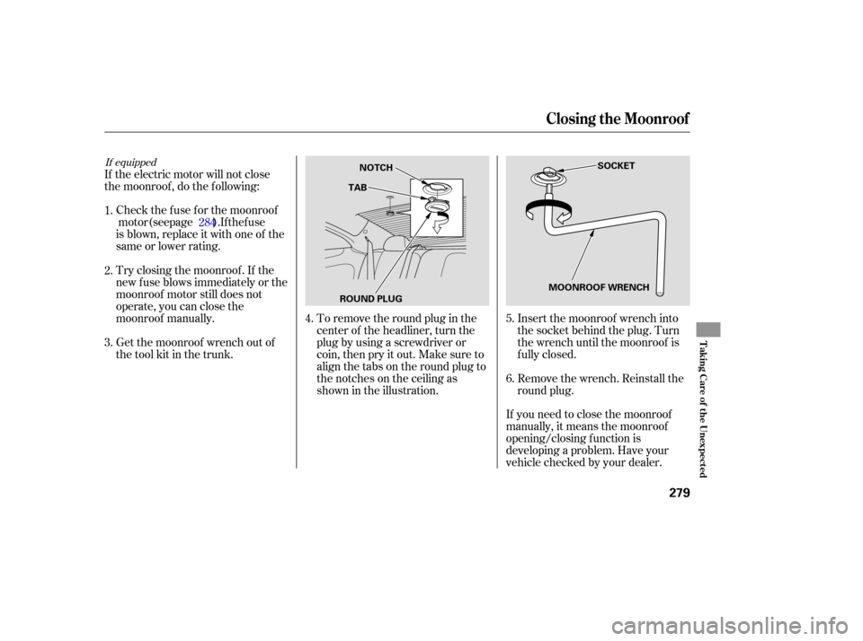
To
remove the round plug in the
center of the headliner, turn the
plug by using a screwd river or
coin, then pry it out. Make sure to
align the tabs on the round plug to
the notches on the ceiling as
shown in the illustration.
If
the electric motor will not close
the moonroof , do the f ollowing:
Check the f use f or the moonroofmotor (see page ). If the fuse
is blown, replace it with one of the
same or lower rating.
Try closing the moonroof . If the
new f use blows immediately or the
moonroof motor still does not
operate, you can close the
moonroof manually.
Get the moonroof wrench out of
the tool kit in the trunk. Insert the moonroof wrench into
the socket behind the plug. Turn
the wrench until the moonroof is
f ully closed.
4.
3. 1.
2.
5.
6.
284
If equipped
Closing t he Moonroof
T aking Care of t he Unexpect ed
279
SOCKET
ROUND PLUG TAB
NOTCH
MOONROOF WRENCH
�����—�����—�����y�
�������������y���
�(���%�������y���������y
Page 282 of 319

The under-hood fuse box is on the
driver’s side. To open it, push the
tabs as shown. If
something electrical in your
vehicle stops working, the first thing
youshouldcheckforisablownfuse.
Determine from the chart on pages
and , or the diagram on the
f use box lid, which f use or f uses
control that device. Check those
f uses f irst, but check all the f uses
bef ore deciding that a blown f use is
the cause. Replace any blown f uses,
and check if the device works.
Turn the ignition switch to the
LOCK (0) position. Make sure the
headlights and all other
accessories are of f .
The interior f use box is on the
driver’s lower lef t side. To remove
the f use box lid, put your f inger in
the notch on the lid, and pull it
upward slightly, then pull it toward
you and take it out of its hinges. The vehicle’s f uses are contained in
two f use boxes.
Remove the cover f rom the f use
box.
1.
2. 283 284
Checking and Replacing Fuses
Fuses
280
INTERIOR
UNDER-HOOD
TAB
NOTCH
�����—�����—�����y�
���������
���y���
�(���%�������y���������y
Page 285 of 319
�µ�µ
�Î
�Î
�Î �Î
�Î �Î
�Î
�Î
�´
�Î
�Î
�Î
No. Amps.
CONT INUED
Amps.
Circuits ProtectedAmps.
No. Circuits Protected
No. Circuits Protected
1: All except U.S. 4-cylinder LX model
2: 4-cylinder models
3: 6-cylinder models
6
7
8
9
10 10 A
7.5 A 15 A
20 A
10 A
30 A
10 A
15 A
10 A Right Headlight Low Beam
Back Up
FI ECU (ECM/PCM)
Condenser Fan
Not Used20 A
30 A
7.5 A 20 A
40 A
40 A
15 A
30 A
30 A
20 A
40 A
40 A
40 A
40 A
100 A
50 A
50 A
11
12
13
14
15
16
17
18
19
20
21
22
23
Cooling Fan
Cooling Fan
MG. Clutch
Horn, Stop
Rear Defroster
Back Up, ACC
Hazard
ABS Motor
VSA Motor
ABS Unit
VSA Unit
Option
Option
Heater Motor
Battery
Not Used
BIG1Main
Power Window Main
1
2
3
4
5 Left Headlight Low Beam
Rear Defroster Coil
Left Headlight High Beam
Small Light
Right Headlight High Beam
2
3
2 3
2 3
1
1
Fuse Locations
T aking Care of t he Unexpect ed
283
UNDER-HOOD FUSE/RELAY BOX
�����—�����—�����y�
�������������y���
�(���%�������y���������y