Page 340 of 484
BE-62
Diagram of acoustical equipment system (continued)
SL SK
SY SJ
fuse ignition switch
ACC ON ST41
small lamp
large lamp
662
5
9
PQ813O57
receiver receiver
12 3
4
56
78912
3454
32 1
5
6 7 8
ignition switch
combined switch
8765
16 15 14
NP12 1143 2
1
9 10
fuse ignition switch
ACC
ONST41
small lamp
large lamp
616
25
934
81
32 5 7
CD device CD device
12 34
567
U912
345
ignition switch
43 21
R6 8
combined switch
8765
16NR14 13 12 11 10 92 3 4N
receiver
small lamp relaysmall lamp relayelectric aerialCD device
batterybattery
fuse
fuse
7
Body Electric System�Acoustical Equipment System
Page 364 of 484
AC-1
Page
Introduction ................................................................. AC-2
Electric circuit diagram of air-conditioning system ...... AC-4
System constitutes ...................................................... AC-8
General introduction .................................................... AC-9
Troubleshooting .......................................................... AC-10
Inspection for refrigerant quantity ................................ AC-11
Compressor ................................................................. AC-12
Liquid container ........................................................... AC-14
Condenser ................................................................... AC-15
Cooling device ............................................................. AC-16
Refrigerant pipeline ..................................................... AC-20
AC
Air-conditioning System
Page 367 of 484
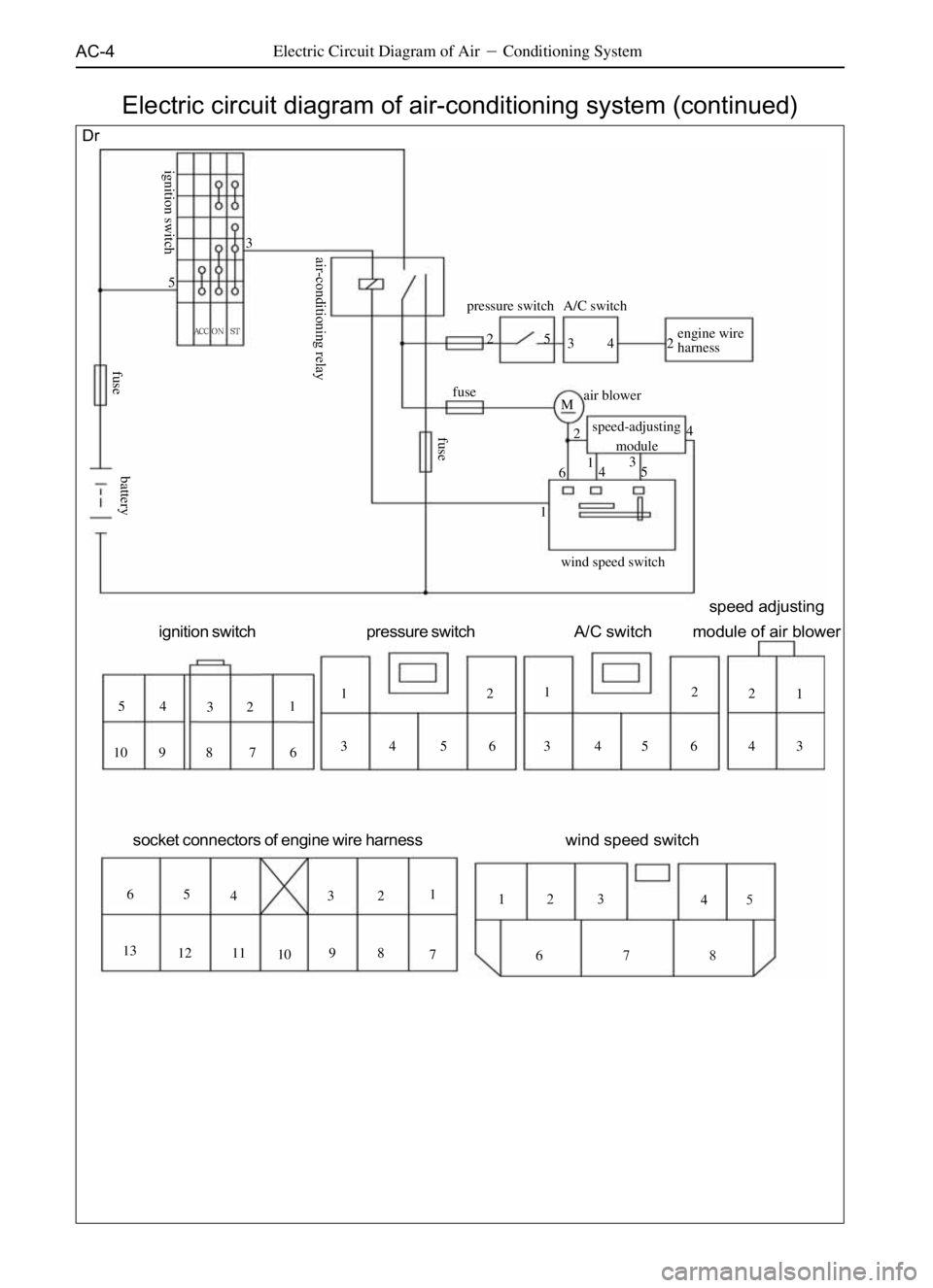
AC-4Electric Circuit Diagram of Air�Conditioning System
Electric circuit diagram of air-conditioning system (continued)
Dr
fuseA/C switch pressure switch
engine wire
harness
air blower
speed-adjusting
module
wind speed switch M2 2
2
2 2
2
2
O 24 4 4 4
4
Q 4
44 3 3
3
3 3 3 3
3
P 5 5
5
5 5 5
5
R 1
1
N 1
1
1
1
N6
6 6
6
6
S 7
7
TU 8
8 9
9 10
10 11 12 13
ignition switch pressure switchA/C switchspeed adjusting
module of air blower
socket connectors of engine wire harnesswind speed switch
lk ^`` p q
fuse ignition switchair-conditioning relayfuse
battery
Page 368 of 484
AC-5Electric Circuit Diagram of Air�Conditioning System
SF
ST
fusethree-state pressure switch
cold-hot
servomotor circular
servomotor mode
servomotor main air-conditioning
control panel
speed
adjusting
module
air blower
b`r
power resistor
water
valve
Mjjj
M
ACCON
+12V 5
R R 5
5 5 5 5
5
5 PP
P P 3
3
3 3 3 3
3
3
3 1
111
1
1
1 N
N N
1
2 2 2 2
2
22 O O OO
4
44 4
4 4 4Q
Q
Q Q
4
6 6
6 6 6
6S S 6
S6
7
7
7 8
88 9
9
9 10
1010
1111
12
13 14 15 16 17 18 1920
20 21 22 23 2423
ignition switch modular air-door motor cold-hot air-door motor air-in motor
three-stage
pressure switch speed adjusting
modul air conditioning
ignition switchsmall light relay
fusefuse electronic fan
water temperature relay
fuse
compressor relayelectromagnetic
fan relay
compressor clutch
24
Electric circuit diagram of air-conditioning system (continued)
battery
18
5
17
16
3
15
19
14
22
1
13
Page 369 of 484
AC-6Air-Conditioning System�(Electric Circuit Diagram)
�S
SL SK SJ
fuse
air-conditioning
request relay
connect with ECUfuseECU
^``lkpq
4
5
1
2
45 6
32
36 54
21
1
2 1
32
ignition switch speed adjusting module
air blower A/C SWITCH pressure switch
1 2 3 4
5 6 7 81 2 3
4 5 61 2 3
4 5 6
1
2 1
2 3 1
2
compressor
electromagnetic fan relay compressor relay
pressure switch fuse
fuse
electromagnetic fan
air-conditioning
request relay
A/Cswitch
blower
air-volume switch
speed-adjusting resistance
heat-sensitive resistance blower relay
charging indicating lamp
ignition switch
air-volume switch Electric circuit diagram of air-conditioning system (continued)
battery
ECU
Page 370 of 484
AC-7Air-Conditioning System�(Electric Circuit Diagram)
compressor
compressor relay
fuse
rearignition switch
electromagnetic
cutoff valve
rear speed-adjusting
resistance temperature controller
rear wind-velocity switch
rear air-conditioning relay
air blower
electromagnetic fan relay
electromagnetic fan
air-conditioning request relay A/C switch
R ECU
pressure switch
speed-adjusting resistance
air
blower
blower relay
(electricity-connecting and
charging indicating lampair-conditioning
request relay
connect with ECU 2
1
312
3
3
3 22
1
1
44
44 1
1 2
23
35
5
56
6 6
4fuse1
1
1
1
1
1
1
1 22 2 22 22 23
3
3
3
3
3
3
3 4444 4 4
5
5
5
5 6
6
6
6 7
7 88
SY
STACC ON
rearignition
switchtemperature
controllerrear wind-
velocity switchrear speed-
adjusting resistancespeed-adjusting
resistanceair-volume
switchA/C switchignition switch
ignition switch
fuse heat-sensitive resistance
(air-volume
switch)
fuse
Electric circuit diagram of air-conditioning system (continued)
battery
ECU
Page 480 of 484
B-2
Disassembling and as-
sembling tools for lock-
ing nut of steering
knuckle3916001
��
Press fitting tool for in-
ner bearing of front wheel
hub3916002
3916003
3916004
3916005
3916006
3916007
3916008
3916009
3916010 Press fitting tool for outer
bearing of front wheel
hub
Disassembling tool of
ball stud
Fixing tool of main teeth
flange of needle bearing
Press fitting tool for steer-
ing knuckle oil seal
Disassembling tool of
shorter liner of lower arm
Mounting tool of shorter
liner of lower arm
Mounting and disassem-
bling tool of long liner of
lower arm
Disassembling tool of
upper arm liner
��
��
��
�
�
��
��
��
��
SST Special Service tool
Diagram Tool name tool number Remark
SST Special Tool�Special Service Tool
Application position
Front axle
Rear axle
2WD 4WD
Page 481 of 484
B-3
Application position
Front axle
Rear axle
2WD 4WD
3916011�
3916012
3916013
3916014
3916015
3916016
3916017
3916018
3916019
3916020 Press fitting tool of up-
per arm liner
Disassembling and as-
sembling tools of wheel
brake cylinder of front
brake caliper
Disassembling tool of
front drive shaft bearing
Pneumatic caliper of
outer sleeve of front drive
shaft
Press fitting casing of
front drive shaft bearing
Disassembling tool of
main teeth oil seal
Press fitting tool of main
teeth oil seal
Disassembling tool of
long semi-axis
Electric cutch tester
Disassembling tool of oil
seal and needle bearingOil seal of long semi-
axis of front axle
Inner oil seal of rear axle
shaft
Needle bearing of long
semi-axis
SST Special tool
Diagram Tool Name tool number Remark
SST Special Tool�Special Service Tool
�
�
�
�
�
�
�
�
�
��
�
�

SL SK
SY SJ
fuse ignition switch
ACC ON ST41
small lamp
large lamp
662
5
9
PQ813O57
receiver receiver
12 3
4
56
78912
3454
32 1
5
6 7 8
ignitio")