Page 280 of 484

BE-2
Brief Introduction
1. Power supply system
The power supply system includes accumulator, generator and its adjustor. Generator is the main power supply; the
accumulator is the auxiliary power supply. The generator, parallel with the accumulator, is equipped with the
adjustor, which is used to maintain the voltage of generator stable when the rotating velocity and the load varies.
2. Starting System
Which includes the direct current motor, drive mechanism and control device, etc. its performance is to start the
engine.
3. Lighting system
Which includes various lighting lamps inside and outside of the body and their control device; they are used mainly
to guarantee safety driving in night.
4. Alarming System
Which includes the electric horn, flasher and various service signal indicating lamps, etc. they are mainly used to
guarantee the physical and driving safe when driving.
5. Auxiliary Electric Appliance System
It includes the electric wiper, air-conditioner, recorder and cigarette lighter, etc.
R
red
R/G
redgreen
socket plugging element plug plugging elementN
2 3
4 5 6 123
4
5
S
socket plugging
elementplug plugging element
1. The codes of sockets of socket plugging element are
complied from left to right.
2. The codes of sockets of socket plugging element are
compiled from right to left.
Remark: all of plugging elements are watched from the in-
wiring direction.
3. Comparison between plug and socket plugging elements
The plug and socket plugging elements are classified accord-
ing to their in-built socket shape.
(a) All of plugging element are marked according to the
opening end and are locked at their tops.
(b) When pulling the plugging element, pull the plugging
element itself instead of wire.
Remark: before pulling the plugging element, check the
plugging element that you want to disconnect first to verify
their classifications.
English letters for wiring colors code:
B =black Bl =blue R =red Br =brown
Lg =reseda V =purple G =green O =orange
W =white Gr =gray P =pink Y =yellow
First letter stands for the basic color, while the second for the
stripe color.
Body Electric System�Brief Introduction
Page 284 of 484
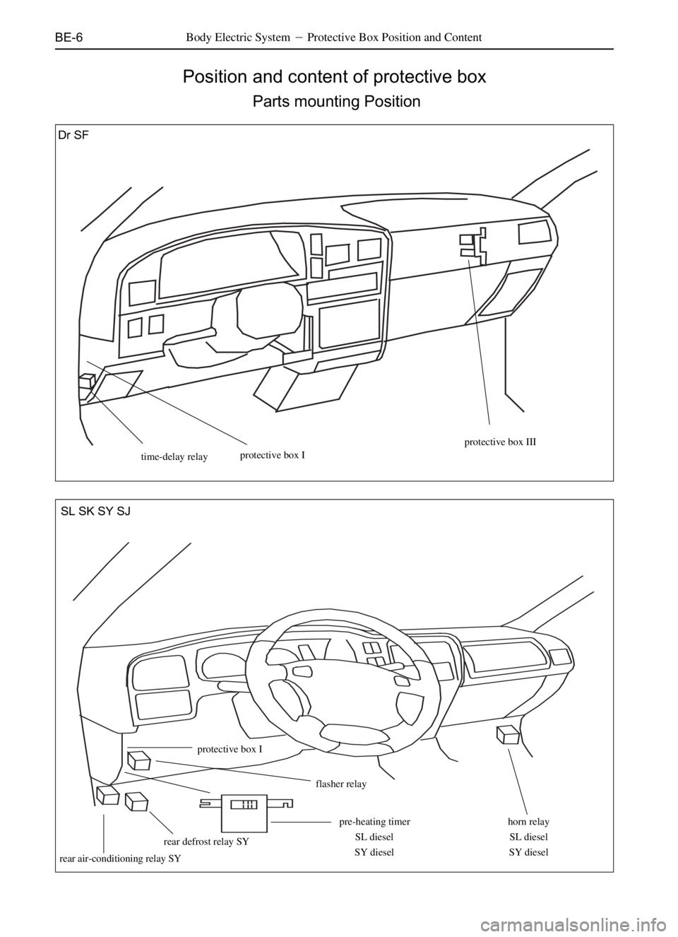
BE-6
Position and content of protective box
Parts mounting Position
Body Electric System�Protective Box Position and Content
time-delay relayprotective box I
protective box III
horn relay
SL diesel
SY dieselpre-heating timer
SL diesel
SY diesel
flasher relay
protective box I
rear defrost relay SY
rear air-conditioning relay SY
SL SK SY SJ Dr SF
Page 290 of 484
BE-12
Protective box II
Body Electric System�Protective Box Position and Content
Dr SF
Fuse Vehicle Relay vehicle
1. Front fog lamp 15A Dr A. electromagnetic fan relay Dr
Unload SF charging relay Dr diesel
2. Electromagnetic fan 15A Dr electric horn relay SF
ECU1 10A SF B. large lamp Dr SF
3. Large lamp 10A Dr C. frost relay Dr SF
Horn 15A SF
4. Horn 15A Dr
Lower beam 10A SF
5. ECU1 10A Dr (1) plugging elements of
wire harness in engine room Dr
Charging 10A Dr diesel none SF
Rear frost 5A SF (2) plugging elements of
wire harness in engine room Dr SF
6. Large lamp 10A Dr (3) plugging elements of
wire harness in engine room Dr SF
ECU2 10A SF
7. Rear frost 10A Dr
Upper beam 10A SF
8. ECU2 10A Dr
Preheating 10A Dr diesel
Front fog lamp 10A SF
9. Fuel pump 10A Dr SF
Unload Dr diesel
�
�
� A
B
C 12 3
45 6
78 9
Page 291 of 484

Fuse Vehicle Relay Vehicle
1. Standby 10A SL SK A.electromagnetic fan relay SL SK
2. Standby 10A SL SK small")
BE-13Body Electric System�Protective Box Position and Content
Protective box II (continued)
Fuse Vehicle Relay Vehicle
1. Standby 10A SL SK A.electromagnetic fan relay SL SK
2. Standby 10A SL SK small lamp relay (SL diesel)
3. Standby 30A SL SK B.electric window relay SL SK
20A (SL diesel) cold start relay (SL diesel)
4. Rear fog lamp 10A SL SK C.frost relay SL SKLeft
large lamp 10A (SL diesel) charging relay) (SL diesel)
5. Front fog lamp 10A SL SK D.blower relay) SL SK
Right large lamp 10A (SL diesel) thermostatic relay (SL diesel)
6. Small lamp 10A SL SK E.small lamp relay SL SK
Air-conditioner 10A (SL diesel) heating relay (SL diesel)
7. Electric horn 10A SL SK F.large lamp relay SL SK
Warm air 20A (SL diesel) G.air-conditioner relay SL SK
8. Electric window 30A SL SK frost relay (SL diesel)
Unloa (SL diesel) H.rain-brusher intermissive relay SL SK
9. A/C 10A SL SK I.diod SL SK
Charging 10A (SL diesel)
10. Air blower 30A SL SK
Electric horn 10A (SL diesel)
11. Electronic fan 10A SL SK
Dual flasher 10A (SL diesel)
12. Right large lamp 10A SL SK
Unload (SL diesel)
13. Left large lamp 10A SL SK
Fog lamp 10A (SL diesel)
14. 60A fuse SL SK
15. 60A fuse SL SK
16. 30A fuse SL SK
17. 30A fuse SL SK
Unload SL diesel
123
H4567
14
15
GEFCD AB 8 9 10 11 12 13
SL SK
17
16
I
Page 292 of 484

3. Standby 30A SY SJ B. electric window relay SY SJ
4. Rear f")
BE-14
Fuse Vehicle Relay Vehicle
1. Standby 10A SY SJ A. electromagnetic fan relay SY SJ
2. Standby 10A SY SJ small lamp relay (SY diesel)
3. Standby 30A SY SJ B. electric window relay SY SJ
4. Rear fog lamp 10A SY SJ cold start relay (SY diesel)
Left large lamp 10A (SY diesel) air-conditioner relay SJ
5. Front fog lamp 10A SY SJ C. frost relay SY SJ
Right large lamp 10A (SY diesel) charging relay (SY diesel)
6. Small lamp 10A SY SJ D. blower relay SY SJ
Air-conditioner 10A (SY diesel) thermostatic relay (SY diesel)
7. Electric horn 10A SY SJ E. small lamp relay SY SJ
Warm air 20A (SY diesel) heating relay (SY diesel)
8. ECM 10A SY SJ rear defrost relay SJ
Unload (SY diesel) F. large lamp SY SJ
9. Fuel pump 10A SY SJ H. rain-brusher intermissive relay SY SJ
Charging 10A (SY DIESEL) I. diode SY SJ
10. Air blower 30A SY SJ
Electric horn 10A (SY diesel)
11. Electronic fan 10A SY SJ
Dual flasher 10A (SY diesel)
12. Right large lamp 10A SY SJ
Rear fog lamp 10A (SY diesel)
13. Left large lamp 10A SY SJ
Front fog lamp 10A (SY diesel)
14. 60A fuse SY SJ
15. 60A fuse SY SJ
16. 30A fuse SY SJ
17. 30A fuse SY SJ
Unload (SY diesel)
Protective box II (continued)
Body Electric System�Protective Box Position and Content
12 3 4
17
1614
15
IH
G
EF CD A
B 5 6 7 8 9 1011 1213
SY SJ
Page 302 of 484
BE-24Body Electric System�Lighting System
Steering and Alarming System
Dr
fuse
horn switch
ON
OFF
flasher
B
Ei
OFF ON
123
steering switch
left right
16
2
9left turn indicating lamp
front left turn lamp
(turn lamp) on left side)
rear left turn lamp
right turn indicating lamp
(right front turn lamp
turn lamp) on right side
(rear right turn lamp)
combination switch lamp)
alarming switch
1
2 3 1 2 3 4 5 6 7
8 9 10 11 12 13 14
15 16 17 18 19 20 21
electric horn
battery alarming lamp switch
Page 304 of 484

BE-26Body Electric System�Lighting System
Inspection on Common Failure
FailurePossible Causes Repairing approaches Remark
Only one lamp doesn�t work Burn off bubble
Grounding failure of socket or wiringChange the bubble
Make reparation as required.
Abnormal steering signal Burn off horn fuse Change the fuse and check to see Dr SF
whether there is short circuit
Failure of steering signal flasher Check the flasher
Failure of steering signal/alarming switch Check the switch
Wiring or groun ding failure Make reparation as required. One side of the steering Failure of steering signal switch Check the switch
signal doesnít flash Wiring or grounding failure Make reparation as required. Alarming lamp doesn�t Change the fuse and check to see Change the fuse and check Dr SF
workBurn off horn fuse whether there is short circuit
Failure of steering signal flasher Check the flasher
Failure of steering signal/alarming switch Check the switch
Wiring or grounding failure Make reparation as required. The front combination Burn off fuse Change the fuselamp don�t work
Failure of large lamp relay Check the relay
Failure of combinationswitch Check the switch
Wiring or grounding failureMake Make reparation as required
Burn off fuse in tail lamp Change the fuse and check
whether there is short circuit
Burn off maxi-fuse Change the maxi-fuse;
Failure of combined switch Check the switch;
Wiring or grounding failure Make reparation as required. Upper beam lamp doesn�t work Failure of combination switch Check the switch
Wiring or grounding failure Make reparation as required
The rear combined tail lampand
license lamp don�t work
Page 346 of 484
BE-68Body Electric System�Wire Harness Distribution
Housing wire harness
1 back-up lamp switch
2 starter
3 starter
4 oil pressure sensor
5 grounding wire
6 grounding wire
7 connected to protective box II
8 protective box II
9 connected to protective box II
10 starter11 air-conditioner compressor12water temperature sensor
13 washer motor
14 right headlamp
15 right lever-shaped lamp
16 electric horn
17 generator
18 left headlamp
19 left lever-shaped lamp
20 front turn lamp of left side
21 connected to protective box I
1
2
P
4 5 6 7
8
V
1011
12
13
14
NR1617
18
192021
Wire harness distribution
aê