Page 280 of 484

BE-2
Brief Introduction
1. Power supply system
The power supply system includes accumulator, generator and its adjustor. Generator is the main power supply; the
accumulator is the auxiliary power supply. The generator, parallel with the accumulator, is equipped with the
adjustor, which is used to maintain the voltage of generator stable when the rotating velocity and the load varies.
2. Starting System
Which includes the direct current motor, drive mechanism and control device, etc. its performance is to start the
engine.
3. Lighting system
Which includes various lighting lamps inside and outside of the body and their control device; they are used mainly
to guarantee safety driving in night.
4. Alarming System
Which includes the electric horn, flasher and various service signal indicating lamps, etc. they are mainly used to
guarantee the physical and driving safe when driving.
5. Auxiliary Electric Appliance System
It includes the electric wiper, air-conditioner, recorder and cigarette lighter, etc.
R
red
R/G
redgreen
socket plugging element plug plugging elementN
2 3
4 5 6 123
4
5
S
socket plugging
elementplug plugging element
1. The codes of sockets of socket plugging element are
complied from left to right.
2. The codes of sockets of socket plugging element are
compiled from right to left.
Remark: all of plugging elements are watched from the in-
wiring direction.
3. Comparison between plug and socket plugging elements
The plug and socket plugging elements are classified accord-
ing to their in-built socket shape.
(a) All of plugging element are marked according to the
opening end and are locked at their tops.
(b) When pulling the plugging element, pull the plugging
element itself instead of wire.
Remark: before pulling the plugging element, check the
plugging element that you want to disconnect first to verify
their classifications.
English letters for wiring colors code:
B =black Bl =blue R =red Br =brown
Lg =reseda V =purple G =green O =orange
W =white Gr =gray P =pink Y =yellow
First letter stands for the basic color, while the second for the
stripe color.
Body Electric System�Brief Introduction
Page 281 of 484
BE-3Body Electric System�Brief Introduction
pull up
pull up
press down press down
Change of fuse and maxi-fuse
Remark: in case of exchanging the fuse or maxi-fuse, the fuse
or maxi-fuse with same rated current should be used.
Notice:
1. Before exchanging the fuse or maxi-fuse, all electric
appliances and ignition switches should be turned off
firstly. And the rated current of fuse or maxi-fuse should
not be exceeded.
2. When disassembling or assembling the fuse, the
disassembly and assembly tools must be used. And they
must be pulled out or plugged in vertically. No bend is
allowed because the bend will make the connecting
terminals depart away, and thus poor connection will
occur. In case the fuse or maxi-fuse is burned, it shows
there is short circuit. In such situation, the systematic
inspection should be conducted by the qualified
technician.
Remark: the disassembly and assembly tools are put on the
protective box cover.
same rated current 10A
10A
Page 282 of 484

BE-4
How to make systematic inspection
The inspection order is a simple troubleshooting approach, which is used to check and diagnose the failure on vehicle
when there is part (wiring and plugging elements excluded) failure in the systematic operation or presupposed
system.
Following items should be considered firstly when checking the failure.
� wiring failure
� open circuit or short circuit of electric wiring
� failure in plugging element connection or terminal connection
� failure of fuse or maxi-fuse
Notice:
1. The inspection is conducted on vehicle when the system is in operation, therefore, security should be
taken into account when checking.
2. Care should be paid not to make short circuit in the system under the condition that the accumulator is
directly connected, and the applicable voltage should be selected correctly.
Voltage inspection
(a) Verify the voltage situation at the inspection spots.
For example:
�Put the ignition switch at�ON� position
�Put the ignition switch and SW1 at �ON�position;
�Put the ignition switch of SW, SW1 and the relay at
�ON� position (SW2 at �OFF� position)
(b) Connect the cathode lead (-) to the normal grounding
place or the cathode terminal of accumulator with the
voltmeter; while connecting the positive lead (+) to the
plugging element or part terminal. Such inspection can
be conducted with the test bubble instead of voltmeter.
Inspection on Conductance and Resistance
(a) Disconnect the terminal or wire of accumulator to guar-
antee there is no voltage between the inspection sports.
(b) Connect the two measuring leads of ohmn meter with the
inspection spots.ohmn meter
SW SW2
electromagnetic coil� relay� SW1�
fuse
IG terminal connected to ignigtion
switch of SW
12
0
0
� �V
Body Electric System�Brief Introduction
Page 283 of 484

is connected with the positive (+) side of diode, and the
positive")
BE-5
If there is diode in the circuit, connect the two leads in reverse
polar and make another inspection. When the cathode lead (-)
is connected with the positive (+) side of diode, and the
positive (+) lead should be connected with the cathode (-) lead
of diode, the diode should conduct, while the two leads
connected to the reverse polar, the diode should not contact.
Remark: the specification may be not same due to different
testing meter types; therefore, the application instruction for
testing meter should be referred before the inspection.
Check the light emitting diode (LED) according to the same
approach for diode inspection.
Remark:
The testing meter should be used the one with 3V voltage or the
one has larger resistance than that in circuit.
If no suitable testing meter is applied, the voltage of accumu-
lator may be added to check the LED to see whether it is
lighted.
(c) Use the voltage or ohmn meter with high-impedance
(min voltage of 10 KV) to diagnose the failure in electric
circuit. Body Electric System�Brief Introduction0
�0 �
K�
K�ohmn meter
diode
0
0
K�
K
�
��
ohmn
LED
digital type
analogue type
�
DCD
C
V
LG terminal of ignition switch
testing bubblefuse box
short circuit�
SW1
short circuit�
disconnection
electromagnetic
coil
short circuit�
disconnection disconnectiong
Check to see whether there is short circuit
(a) Tear down the burned fuse and remove all loads from
the fuse.
(b) Connect the testing bubble at the fuse position;
(c) Verify the situation of testing bubble position:
For example:
�Put the ignition switch of SW at�ON� position;
�Put the ignition switch of SW and SW1 at�ON� position;
�Put the ignition switch of SW, SW1 and Relay at
�ON� position (which connects with the relay), and put
SW2 at �OFF�) position (or disconnect the SW2).
(d) Disconnect or re-connect the plugging elements when
observing the testing bubble. In case the testing bubble
keeps lighting, which shows there is short circuit between
the plugging elements; if the testing bubble extinguishes,
there is short circuit between the plugging elements.
(e) Shake the trouble wire alongside the body to locate the
SW2 electromagnetic
coil
Page 284 of 484
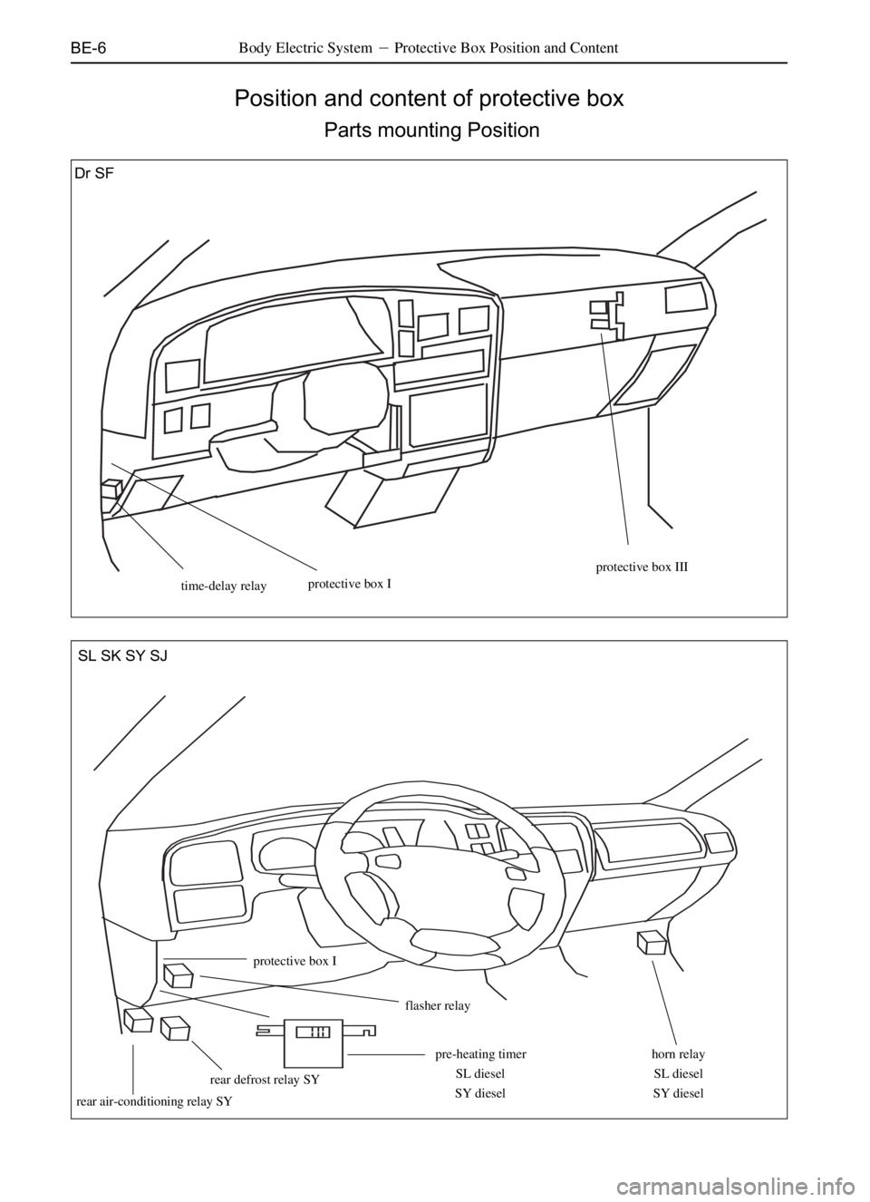
BE-6
Position and content of protective box
Parts mounting Position
Body Electric System�Protective Box Position and Content
time-delay relayprotective box I
protective box III
horn relay
SL diesel
SY dieselpre-heating timer
SL diesel
SY diesel
flasher relay
protective box I
rear defrost relay SY
rear air-conditioning relay SY
SL SK SY SJ Dr SF
Page 285 of 484
BE-7Body Electric System�Protective Box Position and Content
protective box II
preheating relay�diesel�
air-conditioner relay
fuel pump relay
ECU relay
Parts Mounting Position (Continued)
Page 286 of 484
BE-8Body Electric System�Protective Box Position and Content
Content of Protective Box
1 protective box I
fuse
1.Small lamp 10A
2.Rain brus 20A
3.Ceiling lamp 10A
4.(Cigarette lighter) 15A
5.Back -u 15A
6.Brake 10A
7.electric window 30A
8.Instrument 10A
fuel delivery/break electromagnetic valve10A(diesel�
9.Central control lock 15A Dr
A
B
C�
�
1
2
3
456
789
SL SK
U
N
O
V
P
Q
R NM
NN
NO
S
T NP
NQ
FUSE
1. Protection 10A
2. Unload
3. Charging 10A
4. Back-up 10A
5. ECU 10A
6. Unload
7. Rain wiper 10A
8. Stop lamp 10A
9. Ceiling lamp 10A
10. Central control lock 15A
11. Dual flasher 10A
12. EC 10A
13. Fuel pump 10A
14. Cigarette lighter 15Arelay
A electric window relay
B. small lamp relay
C.(flasher)
�(plugging elements of ceiling
lamp wire harness)
�(plugging elements of wire
harness in engine room)
Page 287 of 484
BE-9Body Electric System�Protective Box Position and Content
fuse relay
1. Small lamp 10A A. electromagnetic fan relay
2. Brake 5A B. lasher
3. Ceiling lamp 5A C. electromagnetic fan relay
4. Central control lock 15A D. small lamp relay
5. Electric rocker gear 30A E. electric window relay
6. Dual flasher 10A
7. Cigarette lighter 15A
8. Rear vision mirror 5A (1) plugging elements of ceiling lamp wire harness
9. Unload (2) plugging elements of wire harness at front left door
10. Acoustic device 15A (3)plugging elements of wire harness in engine room
11. Rear window 20A
12. Electromagnetic fan 10A
13. Instrument 5A
14. Back-up lamp 5A
15. Rain brush 10A
16. Steering 5A
17. Unload
18. Unload
��
� A
B
C
E D
123 456
78 9 101112
13 14 15
16 1718
SF
Protective bos I (continued)