Page 167 of 484
SA-56
Mount of Constant Speed Drive Shaft
1. Mount the constant speed drive shaft on the flanges of
the long and short axle shafts.
2. Mount on the front wheel hub and the steering knuckle.
3. Mount on the washer-steering knuckle shaft spline, and
then use the caliper to mount on the retainer ring.
4. Mount on the free hub.
5. Mount on the brake caliper.
Suspension System and Automobile Axle (SF/4WD) �Constant Speed Driving Shaft
Page 190 of 484
SA-79
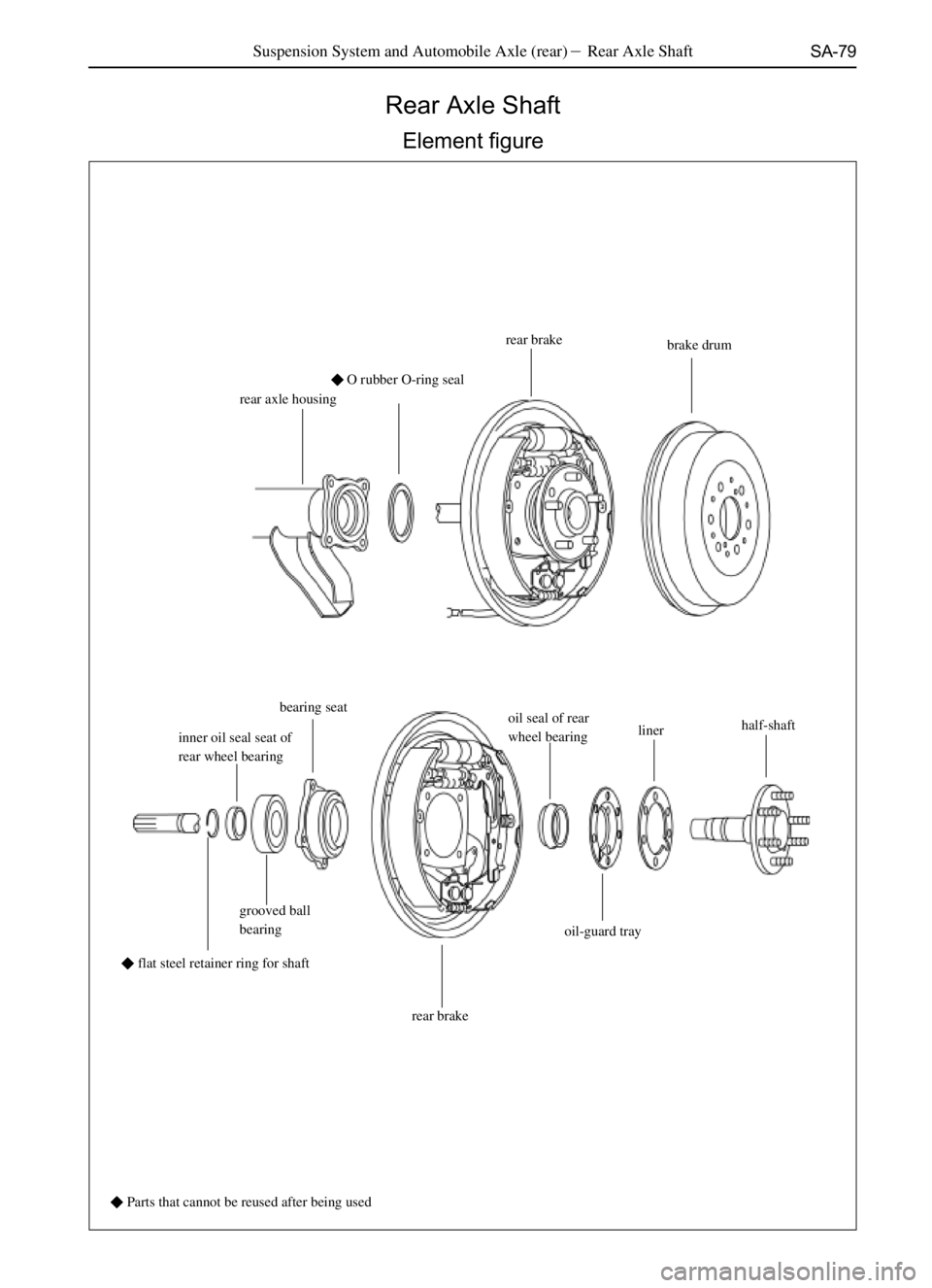
Rear Axle Shaft
Element figure
rear axle housing�O rubber O-ring sealrear brake
brake drum
inner oil seal seat of
rear wheel bearingbearing seat
oil seal of rear
wheel bearinglinerhalf-shaft
grooved ball
bearing
rear brakeoil-guard tray
� Parts that cannot be reused after being used
Suspension System and Automobile Axle (rear)�Rear Axle Shaft
�flat steel retainer ring for shaft
Page 191 of 484

SA-80
Dismantle of Rear half Axle Shaft
1. Tear down the wheels.
2. Tear down the rear brake drum.
3. Tear down the grab end of the bracing wire of hand brake
from the rear brake.
4. Tear down the half-shaft and the rear brake assembly
from the rear axle housing.
5. Tear down the flat steel retainer ring for shaft from the
half-shaft;
Tear down the flat steel retainer ring for shaft with the ring
calipers.
6. Tear down the half-shaft:
Put down a wooden plate on the flat ground, and thrust the end
of spline of half-shaft and rear brake assembly toward the
wooden plate to separate the shaft and the rear brake assembly.
Inspection on and repairing of half-shaft parts
1. Check the wear, damage and swing difference half-shaft
and the flange.
Max shaft run-out: 2 mm
Max flange run-out: 0.2 mm
In case the half-shaft is damaged, or wearied or the measuring
value of the swing difference is excessive, change the half-
shaft.
2. Check he oil seal of rear wheel bearing:
Check to see whether there is wear or damage, and change the
oil seal if necessary.
3. The disassembly of the outer oil seal of rear wheel
bearing;
Tear down the outer oil seal of rear wheel bearing with SST. Suspension System and Automobile Axle (rear)� Rear Half Axle Shaft
Page 192 of 484
 Press out the grooved ball bearing with SST.
(b) Pr")
SA-81
4. Check the grooved ball bearing
Check the grooved bearing to see whether there is damage or
wear.
5. Change the bearing where necessary:
(a) Press out the grooved ball bearing with SST.
(b) Press in the new grooved ball bearing with SST.
6. Mount the new oil seal of rear wheel bearing.
Press in the new oil seal of rear wheel bearing with SST
Coat moderate lithium base grease on the lip open of oil seal.
7. Check the bearing seat.
Check the wear or damage situation.
8. Change the bearing seat where necessary:
(a) Tear down the oil seal of rear wheel bearing and the
grooved ball bearing with SST.
(b) Tap the bolts with copper bar to tear down the bearing seat.
(c) Mount the new grooved ball bearing and the oil seal of
rear wheel bearing on the bearing seat
(d) Press the rear brake, which is put on with bolts, in the
bearing seat.
9. Check the wear or damage of the inner oil seal of the rear
wheel bearing.
10. Change the rear wheel bearing where necessary:
(a) Tear down the oil seal of rear wheel bearing with SST. Suspension System and Automobile Axle (rear)�Rear half Axle Shaft
Page 193 of 484

SA-82
11. Mount the new inner oil seal of rear wheel bearing.
Coat the hyperbolic gear oil on the axle housing where matches
with the oil seal; and plaster the moderate lithium base grease
on the lip open of the oil seal, then put them on the pressure
head and press them in.
Mount of Rear Axle Shaft
1. Press the rear brake and the bearing seat assembly on
the haft shaft.
2. Press the heated inner oil seal seat of rear wheel bearing
on he half shaft;
Notice: the face at the chamfering end of inner oil seal of
rear bearing should contact the oil seal closely, do not
mount it at the incorrect position.
Requirement for heat mount: heat the inner oil seal seat into the
22# oil (GB443-1989) to 100�, after the part is heated
completely, take it out for mount.
3. Mount on the flat steel retaining ring with the ring calipers.
4. Encase the half-shaft rear brake in the axle housing,
screw on the self-locking nut.
Tightening moment�(63-79)N�m
Notice: protect the oil seal lip open, bracing wire assembly
and the oil-guard sleeve.
5. Mount on the hand brake wire and the brake pipe.
6. Mount on the liner and rear brake drum;
7. Make a trial gas exhaust on the braking system, and
8. Mount on the rear wheels.
Suspension System and Automobile Axle (rear) �Rear Half Axle Shaft
Page 205 of 484
N�m
Remark: in case the sealing gask")
SA-94
Mount of Rear Speed Reducer and
Differential Assembly
1. Mount the speed reducer and differential assembly on
the rear axle housing.
Tightening moment�(18-26)N�m
Remark: in case the sealing gasket is mounted, it should be
checked to see whether it is damaged before mounting, if
damaged, change with the new sealing gasket, and the dam-
aged sealing gasket should be clear away; if no sealing gasket
is mounted, no mount is required to mount. Clean the contact
face of the mounted axle housing and coat it with silicon-
rubber plain sealing agent.
2. Connect the drive shaft and flange well and be careful to
align the assembly marks marked when disassembling.
Tightening moment�(69-79)N�m
Screw up the oil drain plug with the Tightening moment
of (140-150)N�m
Mount on the half-shaft and the brake assembly to adjust the
brake oil path so that the wheel brake pump is filled with brake
liquid.
3. Inject in the heavy-duty oil.
Oil brand: heavy-duty oil graded GL-5;
Viscosity: SAE 85W/90
Oil volume: add the oil until it overflows from the oil filler
outlets.
Screw up the oil-filling plug.
Tightening moment�(140-150)N�m
Suspension System and Automobile and Axle (Rear)�Rear speed reducer (Mount of Rear Speed Reducer and Differential Assembly)
Page 212 of 484

BR-1
Braking System
Notice .......................................................................... BR-2
Troubleshooting .......................................................... BR-2
Inspection and Adjustment .......................................... BR-5
Master Cylinder ........................................................... BR-8
Vacuum Booster .......................................................... BR-10
Front Brake ................................................................. BR-13
Dr .......................................................................... BR-13
SF .......................................................................... BR-20
Rear Brake .................................................................. BR-26
Dr .......................................................................... BR-26
SF .......................................................................... BR-34
Load sensing proportion valve .................................... BR-42Page
BR
Page 213 of 484

BR-2Braking System�Notice and Troubleshooting
Notice:
1. Carefully change each part where necessary because any
mistake will affect the brake system properties, and will lead
accidents during driving. And the parts to be changed must
be the same in part number or equal in quality.
2. Keep the parts and each position clean when repairing the
braking system.
Troubleshooting
Trouble Causes Inspection items
Lower or soft pedal Abrasion of brake shoe
Abrasion of brake pad
Oil leakage of braking system
Master cylinder failure
Air in braking system
Wheel-brake cylinder failure
Failure in the automatic regulator of rear brake.Change the brake shoe; Change the brake
pad;
Repair the oil leakage;
Change the master cylinder;
Drain out the air from braking system;
Change the wheel-brake cylinder;
Repair or change the regulator
Brake stagnantPoor adjustment of parking brake;
The bracing wire of parking brake is seized;
Poor adjustment of vacuum booster pushrod)
Failure of the drag spring or the return spring
Pipe line blockage
Brake shoe breakage or deformation
Brake pad breakage or deformation
Seizing of the wheel-brake cylinder or the brake
caliper piston
Automatic regulator breakage
Master cylinder failureAdjust the parking brake;
Make repairing according to real situation;
Adjust the drag rod;
Change the drag spring or the return spring
Make repairing according to real situation;
Change the brake shoe
Change the brake pad
Make repairing according to real situation;
Change the regulator
Change the master cylinder
Over large braking
distanceUnsuitable tire inflation
There is oil stain or lubricant on the brake shoe or
brake pad;
Brake shoe deforms, the brake liner is worn or polished;
Brake pad deforms or is worn or polished;
Brake drum or brake disc deforms
Drag spring or return spring has trouble
The wheel-brake cylinder has trouble
The inner piston of wheel-brake cylinder is seized;
The brake pad is seized;Inflate the air to suitable pressure;
Change the brake shoe or the brake pad;
Change the brake shoe;
Change brake pad
Change the brake drum or the brake disc;
Change the spring;
Change the wheel-brake cylinder;
Change the wheel-brake cylinder
Change the brake pad
The brake pedal is hard
but doesn�t work;There is oil stain or lubricant on the brake shoe or
brake pad;
The brake shoe deforms, brake liner is worn or
polished, or the brake wheel is worn;
The brake pad deforms, or is worn or polished;
The piston of wheel brake pump is seized;
The vacuum booster has trouble
The vacuum degree is unsuitable
The brake pipe line is blockedChange the brake shoe brake pad;
Change the brake shoe
Change the brake pad;
Change the wheel-brake cylinder;
Change the vacuum booster;
Make repairing according to real situation;
Make repairing according to real situation;