Page 243 of 484

BR-32
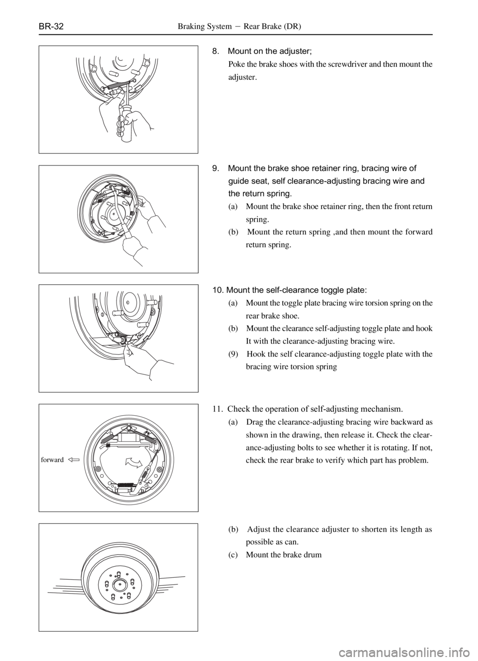
8. Mount on the adjuster;
Poke the brake shoes with the screwdriver and then mount the
adjuster.
9. Mount the brake shoe retainer ring, bracing wire of
guide seat, self clearance-adjusting bracing wire and
the return spring.
(a) Mount the brake shoe retainer ring, then the front return
spring.
(b) Mount the return spring ,and then mount the forward
return spring.
10. Mount the self-clearance toggle plate:
(a) Mount the toggle plate bracing wire torsion spring on the
rear brake shoe.
(b) Mount the clearance self-adjusting toggle plate and hook
It with the clearance-adjusting bracing wire.
(9) Hook the self clearance-adjusting toggle plate with the
bracing wire torsion spring
11. Check the operation of self-adjusting mechanism.
(a) Drag the clearance-adjusting bracing wire backward as
shown in the drawing, then release it. Check the clear-
ance-adjusting bolts to see whether it is rotating. If not,
check the rear brake to verify which part has problem.
(b) Adjust the clearance adjuster to shorten its length as
possible as can.
(c) Mount the brake drum
forward
Braking System�Rear Brake (DR)
Page 251 of 484
BR-40
7.Mount the front brake shoe:
(a) Mount the lower tension spring between the front shoe
and the back shoe.
(b) Mount the front brake shoe in such manner that the end
shoe is inserted in the wheel-brake cylinder, and mount
correctly the adjuster.
(c) Mount the pressure spring, pressure spring cap and
claming pin.
Notice: Do not let the oil or lubricant touch the brake
shoe.
(d) Mount the upper tension spring.
8. Check the operation of self-adjusting mechanism.
(a)Move the parking brake lever of rear brake shoe forward
and backward as shown in the drawing, check the self-
adjusting screw arbor to see whether it can rotate or not,
if not, check the rear brake to see which part has problem.
(b) Adjust the adjuster length and shorten it as can as possible.
(c) Mount the brake drum.
(d) Drag the parking brake lever to the max distance until no
quack-quack is heard. Braking System�Rear Brake (SF)
Page 254 of 484

BR-43Braking System�Load Sensing Proportion Valve
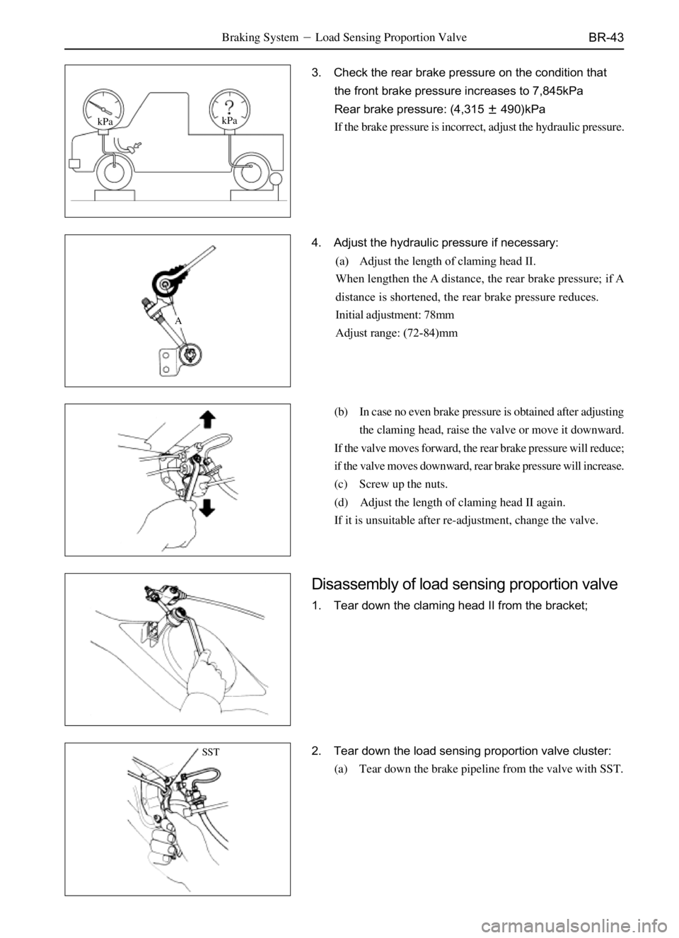
3. Check the rear brake pressure on the condition that
the front brake pressure increases to 7,845kPa
Rear brake pressure: (4,315�490)kPa
If the brake pressure is incorrect, adjust the hydraulic pressure.
4. Adjust the hydraulic pressure if necessary:
(a) Adjust the length of claming head II.
When lengthen the A distance, the rear brake pressure; if A
distance is shortened, the rear brake pressure reduces.
Initial adjustment: 78mm
Adjust range: (72-84)mm
(b) In case no even brake pressure is obtained after adjusting
the claming head, raise the valve or move it downward.
If the valve moves forward, the rear brake pressure will reduce;
if the valve moves downward, rear brake pressure will increase.
(c) Screw up the nuts.
(d) Adjust the length of claming head II again.
If it is unsuitable after re-adjustment, change the valve.
Disassembly of load sensing proportion valve
1. Tear down the claming head II from the bracket;
2. Tear down the load sensing proportion valve cluster:
(a) Tear down the brake pipeline from the valve with SST.
A
SST
kPakPa
Page 277 of 484
SR-21Steering System - Steering Linkage
SST
SST
SST
AA�
BB�
B=B� A=A�
Points on Dismantle and Mount
1. Tear down and connect the swing arm on segmental
gear shaft:
(a) Loosen the swing arm nuts;
(b) Tear down the swing arm from the segmental gear shaft
with SST;
(c) Mount the swing arm on the segmental gear shaft and
mount the spring washer and nut when connecting.
2. Tear down the swing arm from the intermediate lateral
drag rod;
Tear down the swing arm from the intermediate lateral drag
rod with SST.
3. Tear down the side drag rod assembly from the
intermediate lateral drag rod;
Use the SST to tear down the side drag rod assembly from the
intermediate lateral drag rod;
4. Connect the side drag rod assembly:
(a) Screw the two ends in the side drag rod.
Remark: the thread length at the two ends that cannot screw in
the side drag rod should be equal.
Page 442 of 484

B0-59Body�Safety Belt
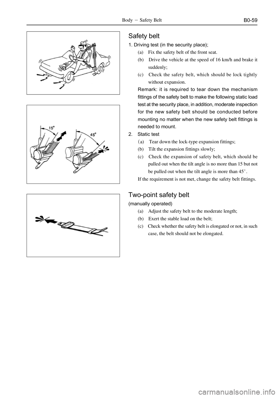
Safety belt
1. Driving test (in the security place);
(a) Fix the safety belt of the front seat.
(b) Drive the vehicle at the speed of 16 km/h and brake it
suddenly;
(c) Check the safety belt, which should be lock tightly
without expansion.
Remark: it is required to tear down the mechanism
fittings of the safety belt to make the following static load
test at the security place, in addition, moderate inspection
for the new safety belt should be conducted before
mounting no matter when the new safety belt fittings is
needed to mount.
2. Static test
�a) Tear down the lock-type expansion fittings;
(b) Tilt the expansion fittings slowly;
(c) Check the expansion of safety belt, which should be
pulled out when the tilt angle is no more than 15 but not
be pulled out when the tilt angle is more than 45�.
If the requirement is not met, change the safety belt fittings.
Two-point safety belt
(manually operated)
(a) Adjust the safety belt to the moderate length;
(b) Exert the stable load on the belt;
(c) Check whether the safety belt is elongated or not, in such
case, the belt should not be elongated.
Page 453 of 484
B0-70
Body Dimension
Engine Room (�)
Vehicle Body�Body Dimension
Dr SF
(point size in 3D)
SL SY
(point size in 3D)
Mark NameBore diameterMark NameBore diameter
H,h Front locating hole of mudguard M8 M,mLocating hole of upper part of
front wall�7
I,iHole of fixing nut of large lamp
M8 N,nFirst mounting hole of wing panel
�
J,jFront locating hole of mudguard
M6
K,k First mounting hole of engine cover M6
L,lFirst mounting hole of wing panel
�10
Remark: the deviation
in length of diagonal
line of engine room
should not be more than
4 mm.
J
K
LIHj
k
l áh
1005
1268582
384
M
Nm
n 728 728
Page 454 of 484
B0-71Body-Body Dismension
SK SJ
(point size in 3D)
O,o
Mark NameBore diameterMark Name Bore diameter
M,m Hole of fixing nut of large lamp�7
N,n First mounting hole of engine cover�
O,o Vertical face of median mesh�
P,pProjection line of vertical face of
median mesh�
Remark: the deviation in length
of diagonal line of engine room
should not be more than 4 mm.
M
Nm
n 845
P,p 711
711
Body Dimension
Engine Room (�)
Page 476 of 484

A-4
Drive Shaft
Torsion moment
Fastening location Applicable vehicle model N*m
Connecting bolt
Fixing bolt of central supporter74�5
40�5 Dr SF SL SK SY SJ
Dr SL SK SY SJ
Inflation pressure of tire
Ground clearance of chassis
Steering angle of inner wheel
Kingpin inner inclination
Outer inclination of front wheel
Mechanical steering
Power steering
Kingpin rear inclination (inclination)
Mechanical steering
Power steering
Toe-in
Error in length between left and right
drag rod
Side slip valueFront:220�0kPa
Back:240�0kPa
Front:250�0kPa
Back:250�0kPa
295mm
255�mm
58.5mm(difference in height between
shaft center of lower arm and wheel
center)
310�mm
295�mm
36��40�
�32�
32��34�
9�30'�5'
14�52'
0�30'�0'
0�10'�0'
0�20'�0'
0�20'�5'
1�50'
-20'
2�5'�5'
2�0'�0'
0-2mm
=2mm
=5m/km
�.5m/km
Suspension System and Automobile Axle
Specification
Item Applicable vehicle model Specification
Dr SL SK SY SJ
SF
Dr
SL SK
SF
SY
SJ
Dr SL SK SY
SF
SJ
Dr SL SK SY
SJ
Dr SL SK SY
Dr
SL SK SY
SJ
Dr SL SK SY
Dr SL SK SY
SJ
Dr SL SK SF SY SJ
Dr SL SK SF SY SJ
Dr SF
SL SK SY SJ
HPM�
Specification of Maintenance and Up-Keeping�Drive shaft, Suspension System and Automobile Axle