Page 270 of 484

Change of power steering liquid
1. Tear down the oil-returning hose from the oil cup to
drain the liquid into the container;
2. Run the engi")
SR-14Steering System�Power Steering (On-Vehicle Inspection)
Change of power steering liquid
1. Tear down the oil-returning hose from the oil cup to
drain the liquid into the container;
2. Run the engine in the idle status, and rotate the
steering wheel toward the max rotating angle for
several times in right or left direction while draining the
liquid, until the oil in steering liquid is drained up.
3. Turn off the engine.
4. Connect the oil-returning pipe and inject the new
power steering liquid in the liquid tank;
Hydraulic oil type: No.8 Liquid drive oil (Q/SH003.01.012-88)
5. Start the engine, and make it running in the idle status.
Rotate the steering wheel to the max rotating angle repeatedly
several times, meanwhile, supplement new power steering
liquid in the liquid tank until there is no foam or turbidities in
the liquid tank, and the oil indicating lamp reaches the marked
range when the engine is turned off.
6. Tighten the liquid tank cover
7. Exhaust the air in the power steering system;
Ai-r bleeding in power steering system
1. Check the liquid level height in the liquid tank
Check the liquid level and, if needed, supplement the liquid.
2. Start the engine in the idle status and rotate the
steering wheel repeatedly to the max rotating angle
several times.
3. Turn off the engine and connect the ethane pipe and
bleeding plug.
4. Start the engine and rotate the steering wheel
repeatedly to the max rotating angle several times.
5. Locate the steering wheel at the intermediate position.
Page 271 of 484
SR-15Steering System�Power Steering (On-Vehicle Inspection)
6. Exhaust the air in steering system:
(a) Loosen the bleeding plug;
(b) Screw up the bleeding plug when there is no air bubble
exhausted from the pipeline.
Notice: take care not let the ethane pipe slide from the
bleeding plug, because the liquid is high in temperature
and pressure.
7. Check to see whether there is air bubble or turbidities
in the oil cup, and ensure the liquid level will not
exceed the max value when the engine stops,
Measure the liquid height under the condition of engine running,
then turn off the engine and measure the liquid height again.
In case any problem is found, repeat the approaches of (5) and
(6) in Power Steering Liquid Change. If the problem still
exists, repair the power steering oil pump.
RPM RPM
Page 272 of 484
SR-16Steering System�Power Steering (Oil Pump of Power Steering)
Oil Pump of Power Steering
Dismantle and Mount of Oil Pump of Power Steering
Gasoline Engine Series
Diesel Engine Series
power steering oil pump
power steering oil pump bracket
belt pulley
driving beltLP oil pipeHP oil pipe
power steering oil pump bracketHP oil pipe
LP oil pipebelt pulley oil cup
power steering oil pump
Page 280 of 484

BE-2
Brief Introduction
1. Power supply system
The power supply system includes accumulator, generator and its adjustor. Generator is the main power supply; the
accumulator is the auxiliary power supply. The generator, parallel with the accumulator, is equipped with the
adjustor, which is used to maintain the voltage of generator stable when the rotating velocity and the load varies.
2. Starting System
Which includes the direct current motor, drive mechanism and control device, etc. its performance is to start the
engine.
3. Lighting system
Which includes various lighting lamps inside and outside of the body and their control device; they are used mainly
to guarantee safety driving in night.
4. Alarming System
Which includes the electric horn, flasher and various service signal indicating lamps, etc. they are mainly used to
guarantee the physical and driving safe when driving.
5. Auxiliary Electric Appliance System
It includes the electric wiper, air-conditioner, recorder and cigarette lighter, etc.
R
red
R/G
redgreen
socket plugging element plug plugging elementN
2 3
4 5 6 123
4
5
S
socket plugging
elementplug plugging element
1. The codes of sockets of socket plugging element are
complied from left to right.
2. The codes of sockets of socket plugging element are
compiled from right to left.
Remark: all of plugging elements are watched from the in-
wiring direction.
3. Comparison between plug and socket plugging elements
The plug and socket plugging elements are classified accord-
ing to their in-built socket shape.
(a) All of plugging element are marked according to the
opening end and are locked at their tops.
(b) When pulling the plugging element, pull the plugging
element itself instead of wire.
Remark: before pulling the plugging element, check the
plugging element that you want to disconnect first to verify
their classifications.
English letters for wiring colors code:
B =black Bl =blue R =red Br =brown
Lg =reseda V =purple G =green O =orange
W =white Gr =gray P =pink Y =yellow
First letter stands for the basic color, while the second for the
stripe color.
Body Electric System�Brief Introduction
Page 286 of 484
BE-8Body Electric System�Protective Box Position and Content
Content of Protective Box
1 protective box I
fuse
1.Small lamp 10A
2.Rain brus 20A
3.Ceiling lamp 10A
4.(Cigarette lighter) 15A
5.Back -u 15A
6.Brake 10A
7.electric window 30A
8.Instrument 10A
fuel delivery/break electromagnetic valve10A(diesel�
9.Central control lock 15A Dr
A
B
C�
�
1
2
3
456
789
SL SK
U
N
O
V
P
Q
R NM
NN
NO
S
T NP
NQ
FUSE
1. Protection 10A
2. Unload
3. Charging 10A
4. Back-up 10A
5. ECU 10A
6. Unload
7. Rain wiper 10A
8. Stop lamp 10A
9. Ceiling lamp 10A
10. Central control lock 15A
11. Dual flasher 10A
12. EC 10A
13. Fuel pump 10A
14. Cigarette lighter 15Arelay
A electric window relay
B. small lamp relay
C.(flasher)
�(plugging elements of ceiling
lamp wire harness)
�(plugging elements of wire
harness in engine room)
Page 287 of 484
BE-9Body Electric System�Protective Box Position and Content
fuse relay
1. Small lamp 10A A. electromagnetic fan relay
2. Brake 5A B. lasher
3. Ceiling lamp 5A C. electromagnetic fan relay
4. Central control lock 15A D. small lamp relay
5. Electric rocker gear 30A E. electric window relay
6. Dual flasher 10A
7. Cigarette lighter 15A
8. Rear vision mirror 5A (1) plugging elements of ceiling lamp wire harness
9. Unload (2) plugging elements of wire harness at front left door
10. Acoustic device 15A (3)plugging elements of wire harness in engine room
11. Rear window 20A
12. Electromagnetic fan 10A
13. Instrument 5A
14. Back-up lamp 5A
15. Rain brush 10A
16. Steering 5A
17. Unload
18. Unload
��
� A
B
C
E D
123 456
78 9 101112
13 14 15
16 1718
SF
Protective bos I (continued)
Page 290 of 484
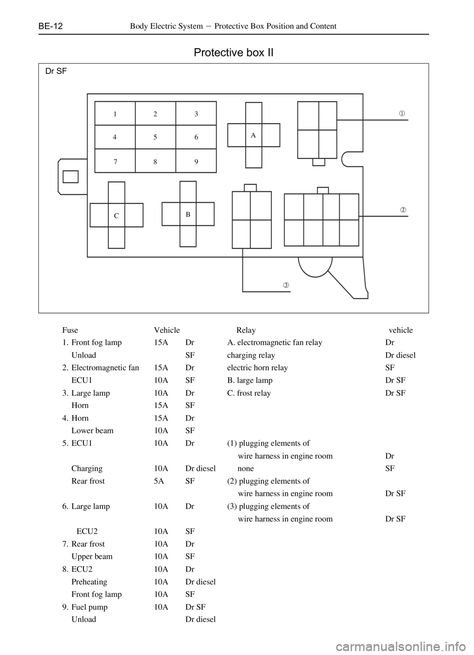
BE-12
Protective box II
Body Electric System�Protective Box Position and Content
Dr SF
Fuse Vehicle Relay vehicle
1. Front fog lamp 15A Dr A. electromagnetic fan relay Dr
Unload SF charging relay Dr diesel
2. Electromagnetic fan 15A Dr electric horn relay SF
ECU1 10A SF B. large lamp Dr SF
3. Large lamp 10A Dr C. frost relay Dr SF
Horn 15A SF
4. Horn 15A Dr
Lower beam 10A SF
5. ECU1 10A Dr (1) plugging elements of
wire harness in engine room Dr
Charging 10A Dr diesel none SF
Rear frost 5A SF (2) plugging elements of
wire harness in engine room Dr SF
6. Large lamp 10A Dr (3) plugging elements of
wire harness in engine room Dr SF
ECU2 10A SF
7. Rear frost 10A Dr
Upper beam 10A SF
8. ECU2 10A Dr
Preheating 10A Dr diesel
Front fog lamp 10A SF
9. Fuel pump 10A Dr SF
Unload Dr diesel
�
�
� A
B
C 12 3
45 6
78 9
Page 310 of 484

BE-32Body Electric System�Combination Instrument
Combination instrument
Electric circuit diagram
��
�� ���� ��
��
��
��
^N ^NS _N _ N P
DraêaáÉëÉärear fog lamp indicating lamp
rear window/defroster indicating lamp
upper beam indicating lamp
front fog-lamp indicating lamp
A13�B3�
connected
with
negative
pole
A10
connected
with
positive
pole
A2
connected
with
negative
polewater
thermometer
tachometer
speedometerconnected with sensor
connected with revolution signal
connected with sensor anode
connected with sensor
fuel gauge
connected with sensor
braking liquid level indicating lamp
parking brake indicating lamp
safety airbag indicating lamp
low oil pressure indicating lamp
engine failure indicating lamp
four wheel drive indicating lamp
generator preheating indicating lamp
fuel alarming indicating lamp
accumulator charging indicating lamp
ABS failure indicating lamp
left turn indicating lamp
right turn indicating lamp
instrument interior
lighting lamp
liquid crystal back-light lamp
A1A16 B1 A5 A6A7 A8 A9 B6 B8 B9B10 B11A12 B4
A15
A14
A10
connected
with
positive
pole
A3
A4
B12
B13
B5
A13�B3�
connected
with
negative
pole
A10
connected
with
positive
pole
A2
connected
with
negative
pole
liquid crystal back-light lampinstrument interior
lighting lamp
rear fog lamp indicating lamp
upper beam indicating lamp
front fog-lamp indicating lamp
water
thermometer
tachometer
speedometer
fuel gaugeconnection with sensor
connected with revolution signal
connected with sensor anode
connected with sensor
connected with sensor
oil-water separation indicating lamp
safety belt indicating lamp
parking brake indicating lamp
braking liquid level indicating lamp
low oil pressure indicating lamp
engine failure indicating lamp
four wheel drive indicating lamp
generator preheating indicating lamp
fuel alarming indicating lamp
accumulator charging indicating lamp
ABS failure indicating lamp
left turn indicating lamp
right turn indicating lamp
A1 A16 B1
A5 A6 A7A8
A9 B6 B8
B9 B10
B11 A4A12 A14 A15B4
A10
connected
with
positive
pole
A3
B12
B13
B5