2006 GREAT WALL HOVER check oil
[x] Cancel search: check oilPage 143 of 425

Caution:
Do not use the Vaseline to fix the washer.
c. Install the transmission rear housing or adaptor rear housing with the new washer.
Caution:
Refer to the description in section 8.3.17 related installation of output flange assembly (rear wheel drive).
d. Install the transmission rear housing (rear wheel drive) or adaptor rear housing (4WD ) and tighten the bolt.
e. Provide the Loctite202 or equivalent sealant to the rear housing or connector and process the installation. Ensure the bolt is
tightened according to the specification. (Refer to Figure 8.1)
7. Front servo assembly
Caution:
Ensure the front servo clamp ring is installed correctly; ensure the ring spring and spark gap points to the bottom. Refer
to Figure 8.22.
The assembly procedure of front servo assembly (Refer to Figure 8.22) is shown as follows:
a. Use the automatic transmission liquid to lubricate the housing O-ring and install it on the housing.
b. Use the automatic transmission liquid to lubricate the housing O-ring and install it on the piston.
c. Install the piston, brake lever, spring, washer, base and fixing ring.
d. Install the piston brake lever assembly on the front servo housing.
e. Install the front servo plug and spring in the box.
f. Install the front servo assembly in the box.
g. Press down the servo housing and install the fixing ring spring of servo housing. Align the spark gap and coil track and ensure
it is installed in the groove properly. Figure 8.22 front servo and brake belt
8. Brake belt assembly
The assembly process of brake belt assembly is shown as follows:
a. Install the reaction reinforcement lever on the housing.
b. Check the brake belt for crack or damage; check the bush and metal back.
c. Install the support retainer on the brake belt (Refer to Figure 8.23).Note that the later transmission modes will not adopt the
support retainer.
Caution:
Place the new brake belt in the automatic transmission liquid for about 5 minutes before install it.
Page 144 of 425

Figure 8.23 Installation of brake belt press lever
d. Install the brake belt on the transmission, ensure it is installed on the correct position.
e. Install the reaction support on the fixing plate and connect it to the brake belt and reinforcement lever. Install the application
support on thea fixing plate and connect it to the brake belt and servo piston bar.
9.C2/clutch C4 assembly
Caution:
Check the piston for crack, especially for piston C2.
Must not mix the clutch piston out and back spring.
Ensure the correct installation of clip ring
The assembly procedure of C2/clutch C4 assembly (refer to 8.24) is shown as follows:
a. Ensure the cleanness of internal oil inlet of cylinder; check the discharge outlet of piston C2 for cleanness; use the transmission
liquid to lubricate the O-ring.
Caution:
The O-ring must not be winded in groove.
Figure 8.24 Typical C2/C4clutch assembly
b. Install the small O-ring in the inner groove; install the large O-ring in the external groove of piston; check the discharge outlet
of C4 piston for cleanness.
c. Use the transmission liquid to lubricate the O-ring; install the small O-ring in the inner groove; install the large O-ring in the
external groove of piston.
d. Make the C2/clutch C4 hole face upwardly; install the clutch cylinder; place the C4 piston in the original position proper for
C2 piston during the calibration..
e. Install the C2/C4 piston assembly on the cylinder; ensure the external hole of cylinder align with the discharge outlet of piston,
until the external diameter of C2 piston enters into the internal diameter of cylinder.
Page 145 of 425
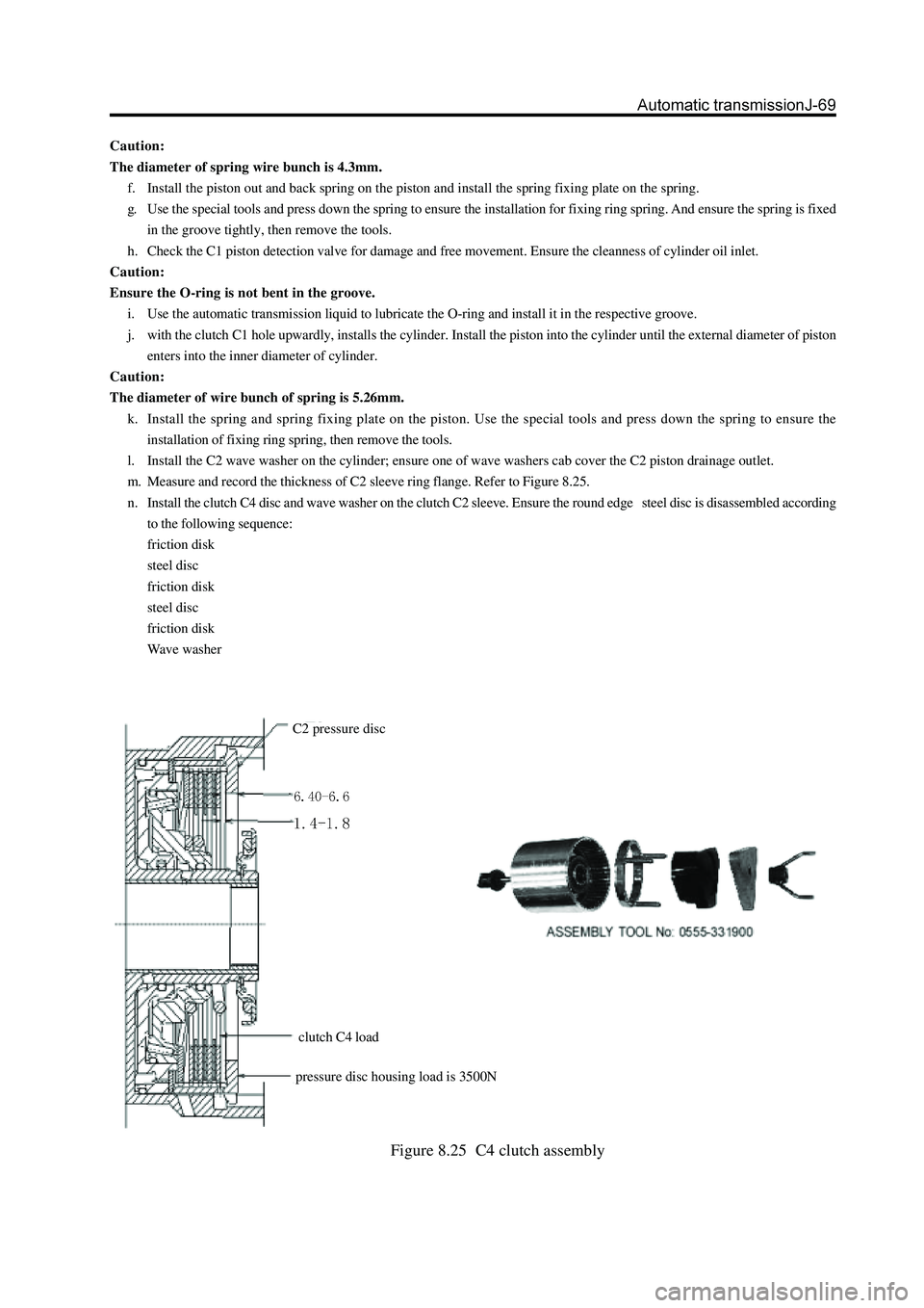
Figure 8.25 C4 clutch assembly
Caution:
The diameter of spring wire bunch is 4.3mm.
f. Install the piston out and back spring on the piston and install the spring fixing plate on the spring.
g. Use the special tools and press down the spring to ensure the installation for fixing ring spring. And ensure the spring is fixed
in the groove tightly, then remove the tools.
h. Check the C1 piston detection valve for damage and free movement. Ensure the cleanness of cylinder oil inlet.
Caution:
Ensure the O-ring is not bent in the groove.
i. Use the automatic transmission liquid to lubricate the O-ring and install it in the respective groove.
j. with the clutch C1 hole upwardly, installs the cylinder. Install the piston into the cylinder until the external diameter of piston
enters into the inner diameter of cylinder.
Caution:
The diameter of wire bunch of spring is 5.26mm.
k. Install the spring and spring fixing plate on the piston. Use the special tools and press down the spring to ensure the
installation of fixing ring spring, then remove the tools.
l. Install the C2 wave washer on the cylinder; ensure one of wave washers cab cover the C2 piston drainage outlet.
m. Measure and record the thickness of C2 sleeve ring flange. Refer to Figure 8.25.
n. Install the clutch C4 disc and wave washer on the clutch C2 sleeve. Ensure the round edge steel disc is disassembled according
to the following sequence:
friction disk
steel disc
friction disk
steel disc
friction disk
Wave washer
C2 pressure disc
pressure disc housing load is 3500N
clutch C4 load
Page 151 of 425
e. If need to install the new friction disk, please remove the clutch assembly and immerse the friction assembly into the
transmission fluid for 5 minutes at least before the installation.
f. Check whether the clutch C1 wheel axle is matched with the overspeed shaft. It should replace the wheel axle and wheel axle
assembly if loose.
g. Coat the small nylon thrust insulation plate with the Vaseline and installs it on the overspeed shaft. Refer to Figure 8.19.
h. It should be carefully when install the overspeed shaft on the C1 cylinder to avoid the damage of sealing ring.
i. Use the Vaseline to install the small copper C1 wheel axle thrust washer, shown as Figure 8.19.
j. Check the input shaft for problem. Install the input shaft on the cylinder and use the ring spring to install the wire safety of
input shaft and cylinder. Ensure the coil is in groove completely.
k. Use the petroleum jelly to install the gasket and place it on the input shaft.
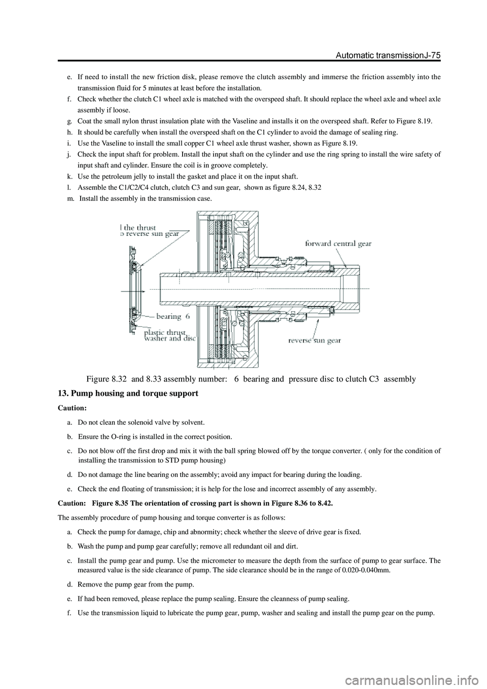
l. Assemble the C1/C2/C4 clutch, clutch C3 and sun gear, shown as figure 8.24, 8.32
m. Install the assembly in the transmission case.
Figure 8.32 and 8.33 assembly number: 6 bearing and pressure disc to clutch C3 assembly
13. Pump housing and torque support
Caution:
a. Do not clean the solenoid valve by solvent.
b. Ensure the O-ring is installed in the correct position.
c. Do not blow off the first drop and mix it with the ball spring blowed off by the torque converter. ( only for the condition of
installing the transmission to STD pump housing)
d. Do not damage the line bearing on the assembly; avoid any impact for bearing during the loading.
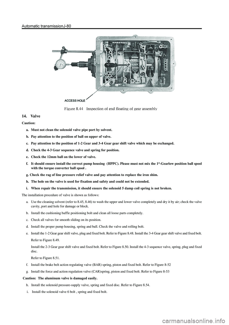
e. Check the end floating of transmission; it is help for the lose and incorrect assembly of any assembly.
Caution: Figure 8.35 The orientation of crossing part is shown in Figure 8.36 to 8.42.
The assembly procedure of pump housing and torque converter is as follows:
a. Check the pump for damage, chip and abnormity; check whether the sleeve of drive gear is fixed.
b. Wash the pump and pump gear carefully; remove all redundant oil and dirt.
c. Install the pump gear and pump. Use the micrometer to measure the depth from the surface of pump to gear surface. The
measured value is the side clearance of pump. The side clearance should be in the range of 0.020-0.040mm.
d. Remove the pump gear from the pump.
e. If had been removed, please replace the pump sealing. Ensure the cleanness of pump sealing.
f. Use the transmission liquid to lubricate the pump gear, pump, washer and sealing and install the pump gear on the pump.
Page 152 of 425
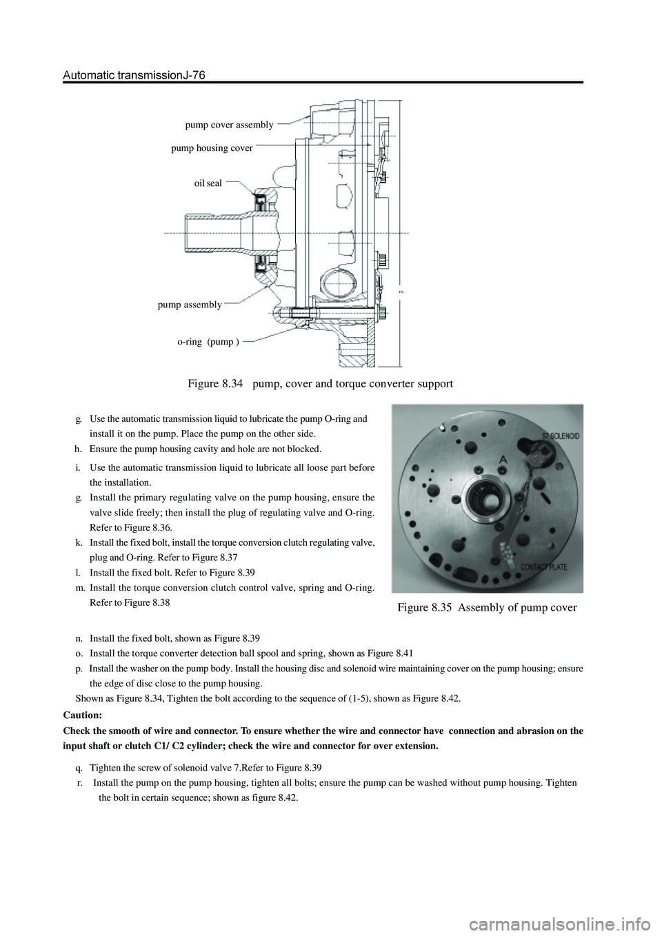
Figure 8.34 pump, cover and torque converter support
g. Use the automatic transmission liquid to lubricate the pump O-ring and
install it on the pump. Place the pump on the other side.
h. Ensure the pump housing cavity and hole are not blocked.
Figure 8.35 Assembly of pump cover
i. Use the automatic transmission liquid to lubricate all loose part before
the installation.
g. Install the primary regulating valve on the pump housing, ensure the
valve slide freely; then install the plug of regulating valve and O-ring.
Refer to Figure 8.36.
k. Install the fixed bolt, install the torque conversion clutch regulating valve,
plug and O-ring. Refer to Figure 8.37
l. Install the fixed bolt. Refer to Figure 8.39
m. Install the torque conversion clutch control valve, spring and O-ring.
Refer to Figure 8.38pump cover assembly
pump housing cover
oil seal
pump assembly
o-ring (pump )
n. Install the fixed bolt, shown as Figure 8.39
o. Install the torque converter detection ball spool and spring, shown as Figure 8.41
p. Install the washer on the pump body. Install the housing disc and solenoid wire maintaining cover on the pump housing; ensure
the edge of disc close to the pump housing.
Shown as Figure 8.34, Tighten the bolt according to the sequence of (1-5), shown as Figure 8.42.
Caution:
Check the smooth of wire and connector. To ensure whether the wire and connector have connection and abrasion on the
input shaft or clutch C1/ C2 cylinder; check the wire and connector for over extension.
q. Tighten the screw of solenoid valve 7.Refer to Figure 8.39
r. Install the pump on the pump housing, tighten all bolts; ensure the pump can be washed without pump housing. Tighten
the bolt in certain sequence; shown as figure 8.42.
Page 156 of 425
14. Valve
Caution:
a. Must not clean the solenoid valve pipe port by solvent.
b. Pay attention to the position of ball on upper of valve.
c. Pay attention to the position of 1-2 Gear and 3-4 Gear gear shift valve which may be exchanged.
d. Check the 4-3 Gear sequence valve and spring for position.
e. Check the 12mm ball on the lower of valve.
f. It should ensure install the correct pump housing (HPPC). Please must not mix the 1
st-Gearlow position ball spool
with the torque converter ball spool .
g. Check the rag of line pressure relief valve and pay attention to replace the iron shim.
h. The hole on the valve is used for fixation and safety and could not be extended.
i . When repair the transmission, it should ensure the solenoid 5 damp coil spring is not broken.
The installation procedure of valve is shown as follows:
a. Use the cleaning solvent (refer to 8.45, 8.46) to wash the upper and lower valve completely and dry it by air; check the valve
cavity, port and hole for damage or block.
b. Install the cushioning baffle positioning bolt and clean all loose parts completely.
c. Check all valves for smooth sliding on its position.
d. Install the proper pump housing, spring and ball. Check the valve and rolling bolt.
e. Install the 1-2 Gear gear shift valve, plug and fixed bolt. Refer to Figure 8.48. Install the 3-4 Gear gear shift valve and fixed bolt.
Refer to Figure 8.49.
Install the 2-3 Gear gear shift valve and fixed bolt. Refer to Figure 8.50. Install the 4-3 sequence valve, spring, plug and fixed
disc.
Refer to Figure 8.51.
f. Install the brake belt action regulating valve (BAR) spring, piston and fixed bolt. Refer to Figure 8-52
g. Install the force and action regulation valve (CAR)spring, piston and fixed bolt. Refer to Figure 8-53
Caution: The aluminum valve is damaged easily.
h. Install the solenoid pressure-supply valve, spring and fixed disc. Refer to Figure 8.54.
i. Install the solenoid valve 6 bolt , spring and fixed bolt.
Page 162 of 425

Figure 8.59 Bushing of engine oil filter
Figure 8.60 Installation of engine oil filter
Figure 8.61 Tightening sequence of oil pan bolt
It should abide by follows when assemble the oil filter and oil sump tank (Refer to Figure 8.59and Figure 8.60):
a. Use the automatic transmission liquid to lubricate the spring ring of gasket of lubrication oil.
b. Install the oil filter on the valve carefully. During the installation, the socket must be inclined. Refer to Figure 8.59.
c. Fix the oil cleaner assembly.
d. Check whether the magnet is installed in the recess on the corner of oil bottom shell.
e. Assemble the groove on the oil bottom shell. The groove must be bent during the installation.
Page 174 of 425
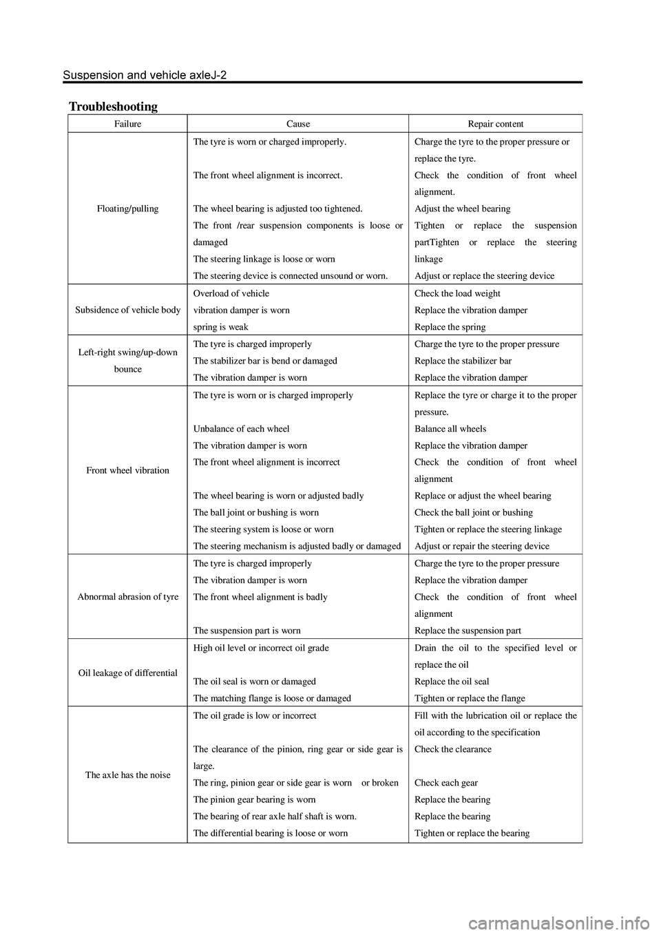
Troubleshooting
Failure Cause Repair cont ent
Floating/pulling The t yre is worn or charged improperly.
The front wheel alignment is incorrect.
The wheel bearing is adjusted too tightened.
The front /rear suspension components is loose or
damaged
The steering linkage is loose or worn
The steering device is connect ed unsound or worn. Charge the t yre to the prop er pressur e or
repla ce the t yre.
Check the condition of front wheel
alignment.
Adjust the wheel bearing
Tighten or replace the suspension
partTighten or replace the steering
linkage
Adjust or replace the steering device
Subsidence of vehicle body Overload of vehicle
vibration damper is worn
spring is weak Check the load weight
Replace the vibration damper
Replace the spring
Left-right swing/up-down
bounce The t yre is charged improperly
The stabilizer bar is bend or damaged
The vibration damper is worn Charge the t yre to the prop er pressur e
Replace the stabilizer bar
Replace the vibration damper
Front wheel vibration The t yre is worn or is charged improperly
Unbalance of each wheel
The vibration damper is worn
The front wheel alignment is incorrect
The wheel bearing is worn or adjusted badly
The ball joint or bushing is worn
The steering system is loose or worn
The steering mechanism is adjusted badly or damaged Repla ce the t yr e or char ge it to the prop er
pressure.
Balance all wheels
Replace the vibration damper
Check the condition of front wheel
alignment
Replace or adjust the wheel bearing
Check the ball joint or bushing
Tighten or replace the steering linkage
Adjust or repair the steering device
Abnormal abrasion of tyre The t yre is charged improperly
The vibration damper is worn
The front wheel alignment is badly
The suspension part is worn Charge the t yre to the prop er pressur e
Replace the vibration damper
Check the condition of front wheel
alignment
Replace the suspension part
Oil leakage of differential High oil level or incorrect oil grade
The oil seal is worn or damaged
The matching flange is loose or damaged Drain the oil to the specified level or
repla ce the oil
Replace the oil seal
Tighten or replace the flange
The axle has the nois e The oil grade is low or incorrect
The clearance of the pinion, ring gear or side gear is
large.
The ring, pinion gear or side gear is worn or broken
The pinion gear bearing is worn
The b earing of rear axle half shaft is worn.
The differential b earing is loos e or worn Fill with the lubrication oil or replace the
oil according to the specification
Check the clearance
Check each gear
Replace the bearing
Replace the bearing
Tighten or replace the bearing