Page 324 of 484
BE-46Body Electric System�Wiping and Washing System
Parts inspection
Brusher switch conductance situation
pi=ph=pv=pg
123 456
78 9 101112Terminal
switch position
MIST
OFF
INT
LO
HI
Washing1
2P4
567
W/B Gr/R Gr/Br Gr/Bl Gr/G GrdêL_ê
aê
pc
1 2 3 4 5 S 7
8 9 10 11 12 13 14
15 16 17 18 19 20 21Terminal
switch position
OFF
INT
LO
HI
Washing61413 21 20
Gr Gr/G Gr/Br Gr/Bl Gr/B
1 2 P 4 5 6 7
8 9 10 11 NO 13 14
15 16 17 18 19 20 21Terminal
switch position
OFF
INT
LO
HI
Washing614132120
Gr/R Gr/G Gr/Br Gr/Bl Gr/B
Page 325 of 484
BE-47Body Electric System�Wiping and Washing System
Brusher switch conductance situation (continued)
In case the conductance situation fails to satisfy the requirements in the above-mentioned drawing, change the switch.
Conductance Situation of Rear Brusher
Where the conductance fails to satisfy the requirements in the above-mentioned drawing, change the switch.
SY SJ
1 2 3 4
5 6 7 8Terminal
switch position
OFF
ON18
765
R/Y B G/W Bl/Y B/Y
SYDiesel
1 2
3 4
5 6 7 8Terminal
switch position
OFF
ON1
876
R
R/Y B G/R Bl/Y B/Y
SLDiesel SYDiesel
123 456
78 9 101112Terminal
switch position
MIST
OFF
INT
LO
HI
Washing12
34567
Bl/B Lg/R Lg/W Bl/Y Bl Bl/O Lg/W
Page 326 of 484
 from accumulator, and
the cathode lead to terminal")
BE-48Body Electric System�Wiping and Washing System
In low-speed operation
Check the front brusher motor
Connect the anode lead to the terminal 2 (1) from accumulator, and
the cathode lead to terminal 3, at this time, the front wiper motor
should be in low-speed operation, otherwise change the front
brusher motor.
In high-speed operation
Connect the anode lead to the terminal 1(2) from the accumulator,
and cathode lead to terminal 3, in such condition, the front wiper
motor should be in high-speed operation.
In case the operation fails to meet the requirement, change the front
wiper motor.
in operation�stop running at the stop position
a. Run the front wiper motor at low speed and stop it at any
positions excluding the stop position by disconnect the
anode lead from the terminal 2 (1).
b. Connect the terminals 2 and 5.\
c. Connect the anode lead to the terminal 6 (4) from the
accumulator, and the cathode lead to terminal 3, check
whether the wiper motor parks at the stop position after
it running for another time, if the requirement is not
satisfied, change the front brusher motor.
Remark: items in parenthesis is for Dr and SF.
Rear brusher motor inspection
Connect the anode lead to the terminal 3 from the accumulator, and
the cathode lead to terminal 4, at this time, the wiper motor will be
in normal operation, disconnect the terminal 3, the rear wiper motor
should stop running at any position excluding the stop position.
1
2
3
4 1
2 3
4 5 61
2 3
4 5
61 2
3
4
5 6
1 2
3
4 5
6
Page 327 of 484
BE-49Body Electric System�Wiping and Washing System
Connect the anode lead to terminal 3 from the accumulator, and
cathode lead with terminal 4, at this time, the wiper motor should
be in normal operation, under such condition, disconnect the
terminal 3, which is connected with terminal 1, and the anode lead
is connected to the terminal 2, in such case, the rear wiper motor
should stop running at the stop position.
In case the operation fails to satisfy the specified requirement,
change the rear wiper motor.
Inspection on Washer Motor
Connect the anode lead to the terminal 1 from the accumulator, and
the cathode lead to the terminal 2, at this time the washer motor
should be in normal operation.
Notice: this test should be finished rapidly (within 20 seconds).
In case the operation fails to meet the specified requirement, change
the washer motor.
1
21
2
3 4
Page 328 of 484
BE-50Body Electric System�Central Control Lock and Electric Rocker Gear System
Central control lock and electric rocker gear system
Part Mounting position
SL SK SY SJ Dr SF
Central control lock box
Central control lock box
Page 329 of 484
BE-51Body Electric System�Central Control Lock and Electric Rocker Gear System
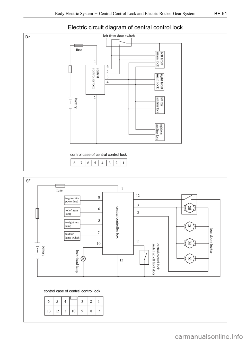
Electric circuit diagram of central control lock
aê
pc
fuse
21
6
5
3
4 left front door switchleft front
main lock
control case of central control lock
1 2 3 4 5 6 7 8
fuse
M M M M
to generator
power lead
to left turn
lamp
to right turn
lamp
to door
lamp switch
control case of central control lock
1 2 3 4 5 6
7 8 9 10 a 12 131
6
5
7
10
132 3 12
11
central
controller box
batterylock-head lamp
battery central controller box
central control lock
switch at left front door
four doors locker
8
right front
main lock
left rear
auxiliary lockright rear
auxiliary lock
Page 330 of 484

BE-52Body Electric System�Central Control Lock and Electric Rocker Gear System
Definition for connecting wire of central control lock
1. Y/V Connect the power to the cell anode on vehicle, in front of which a fuse of 15 A should be set, and
anode of 12V when the motor is started, the voltage should not less than 10V
2. B1 Unlocking output of the locking wire of the CCL actuator, and the grounding wire at the normally
central control lock: closed contact inside the relay will contact with the normally opening contact at
the common spots inside relay when unlocking with REMOTE CONTROLLER
or manually, the wire will output 12 V voltage.
3. LG locking signal of The CCL locking signal is connected to the unlocking wire of actuator of CCL,
central control lockand the normally closed contact in the interior relay is grounding wire, which will
output 12 V voltage when unlocking with REMOTE CONTROLLER or manually
and the common spots of relay contacting the normally opening contact.
4. non-connection There is no wire connected at present
5. G/R Right turn lampConnected to the anode wire of the right turn lamp on the vehicle, and it will output
12 V voltage in operation.
6. G/Y Left turn lamp Connected to the anode wire of left turn lamp on the vehicle, and it will output
12 V voltage when in operation
7. Br Negative input ofWhich is connected to the door switch and it is grounding when the door is
door switch opened (the indoor lamp will light)
8. GD ON power check cable Connected to the ON wire of the locking door( there will be 12 v voltage when
rotating the key at �ON� position.
9. Non-connection This wire is not connected temporarily
10. GD/B Lock head lamp outputThere will be 12 V voltage outputted in this wire when opening the door, and will
be powered off (no output) ten seconds later after the door is closed
12. Y/B Locking signal Connected to the locking signal wire of CCL at the left front door, and connect
to the grounding wire when in operation.
13. B Power cathode Connect to the body (grounding wire) it should be as short as possible, because
the overlong wire will produce the interference source. SF
13P
1
2
3
4
5
6
7
8
9
10
11
12
13Power anode 12 V
unlocking signal of central control lock
locking signal of central control lock
no signal
right turn lamp
left turn lamp
negative input of door switch
ON power check cable
no connection
lock head lamp
unlocking signal
locking signal
power cathode
MK
Remark: the inner switch in actuator should be
connected when the actuator is in the locking status
Remark: In case the actuator is in locking status,
connect the switch inside.
ON wire connected to key
hNOs
hj
left front CCL switch
1 2 3 4 5 6
7 8 9 10 11 12 13
Page 331 of 484
BE-53Body Electric System�Central Control Lock and Electric Rocker Gear System
Electric circuit diagram of central control lock (continued)
SL SK
pv
fuse
8
76
5
4
3
left front door
main lock
right front door
main lockleft rear door
auxiliary lockright rear door
auxiliary lock
control case of central control lock
123456 78
fuse
ignition switch
ACCONST
111
10
8 91
6
4
5
3
7
12
left front main
lockright front
main lock
left rear
auxiliary lockright rear
auxiliary lock
ignition switchcontrol case of central control lock
1 2 3 4
5 6 7 8123 45
6789101112
battery door lamp switch
speed sensor central
controller box turn lamp
battery central
controller box