Page 498 of 600
Uniform Tire Quality Grading
Quality grades can be found where applicable on the
tire sidewall between tread shoulder and maximum
section width. For example:
Treadwear 200 Traction AA Temperature A
The following information relates to the system
developed by the United States National Highway
Traffic Safety Administration, which grades tires by
treadwear, traction and temperature performance.
(This applies only to vehicles sold in the United States.)
The grades are molded on the sidewalls of most
passenger car tires. The Uniform Tire Quality Grading
system does not apply to deep tread, winter-type
snow tires, space-saver or temporary use spare tires,
tires with nominal rim diameters of 10 to 12 inches
(25 to 30 cm), or to some limited-production tires.
While the tires available on General Motors passenger
cars and light trucks may vary with respect to these
grades, they must also conform to federal safety
requirements and additional General Motors Tire
Performance Criteria (TPC) standards.
Treadwear
The treadwear grade is a comparative rating based on
the wear rate of the tire when tested under controlled
conditions on a specied government test course.
For example, a tire graded 150 would wear one and
a half (1.5) times as well on the government course as
a tire graded 100. The relative performance of tires
depends upon the actual conditions of their use,
however, and may depart signicantly from the norm
due to variations in driving habits, service practices and
differences in road characteristics and climate.
Traction – AA, A, B, C
The traction grades, from highest to lowest, are AA, A,
B, and C. Those grades represent the tire’s ability
to stop on wet pavement as measured under controlled
conditions on specied government test surfaces of
asphalt and concrete. A tire marked C may have poor
traction performance. Warning: The traction grade
assigned to this tire is based on straight-ahead braking
traction tests, and does not include acceleration,
cornering, hydroplaning, or peak traction characteristics.
5-86
Page 504 of 600
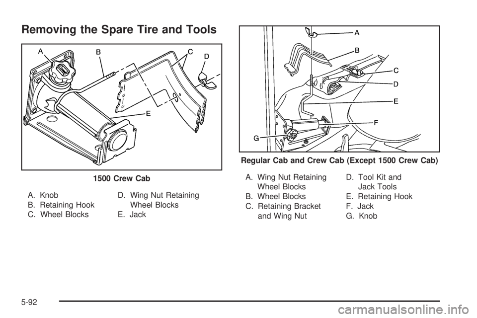
Removing the Spare Tire and Tools
A. Knob
B. Retaining Hook
C. Wheel BlocksD. Wing Nut Retaining
Wheel Blocks
E. JackA. Wing Nut Retaining
Wheel Blocks
B. Wheel Blocks
C. Retaining Bracket
and Wing NutD. Tool Kit and
Jack Tools
E. Retaining Hook
F. Jack
G. Knob 1500 Crew Cab
Regular Cab and Crew Cab (Except 1500 Crew Cab)
5-92
Page 506 of 600
For regular cab models, the equipment you will need is
behind the passenger’s seat. For extended and crew
cab models, the equipment is on the shelf behind
the passenger’s side second row seat.
1. If there is a cover, move the seats forward and turn
the wing nut on the cover counterclockwise to
remove it. For crew cab models, pull up the second
row seat with the loop at the base of the seat
cushion to access the tools.
2. Turn the knob on the jack counterclockwise to lower
the jack head to release the jack from its holder.
3. Remove the wheel blocks and the wheel block
retainer by turning the wing nut counterclockwise.
4. Remove the wing nut used to retain the storage
bag and tools by turning it counterclockwise.You will use the jack handle extensions and the wheel
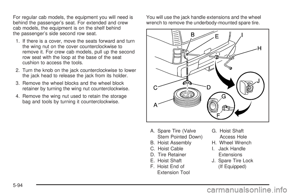
wrench to remove the underbody-mounted spare tire.
A. Spare Tire (Valve
Stem Pointed Down)
B. Hoist Assembly
C. Hoist Cable
D. Tire Retainer
E. Hoist Shaft
F. Hoist End of
Extension ToolG. Hoist Shaft
Access Hole
H. Wheel Wrench
I. Jack Handle
Extensions
J. Spare Tire Lock
(If Equipped)
5-94
Page 507 of 600
1. Open the spare tire lock cover on the bumper and
use the ignition key to remove the lock, if equipped
with a spare tire lock (J).
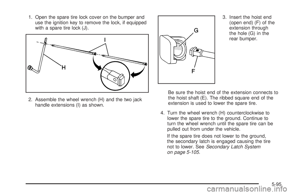
2. Assemble the wheel wrench (H) and the two jack
handle extensions (I) as shown.3. Insert the hoist end
(open end) (F) of the
extension through
the hole (G) in the
rear bumper.
Be sure the hoist end of the extension connects to
the hoist shaft (E). The ribbed square end of the
extension is used to lower the spare tire.
4. Turn the wheel wrench (H) counterclockwise to
lower the spare tire to the ground. Continue to
turn the wheel wrench until the spare tire can be
pulled out from under the vehicle.
If the spare tire does not lower to the ground,
the secondary latch is engaged causing the tire
not to lower. SeeSecondary Latch System
on page 5-105.
5-95
Page 508 of 600
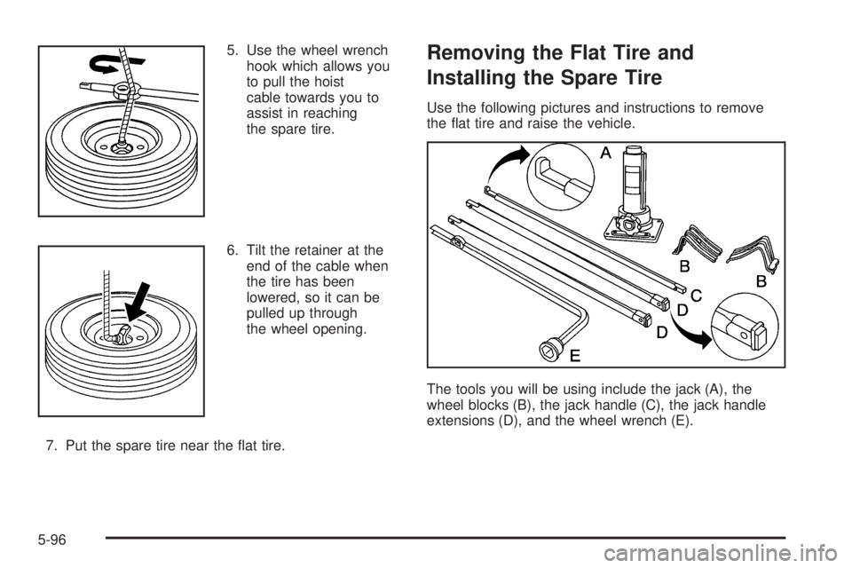
5. Use the wheel wrench
hook which allows you
to pull the hoist
cable towards you to
assist in reaching
the spare tire.
6. Tilt the retainer at the
end of the cable when
the tire has been
lowered, so it can be
pulled up through
the wheel opening.
7. Put the spare tire near the at tire.Removing the Flat Tire and
Installing the Spare Tire
Use the following pictures and instructions to remove
the at tire and raise the vehicle.
The tools you will be using include the jack (A), the
wheel blocks (B), the jack handle (C), the jack handle
extensions (D), and the wheel wrench (E).
5-96
Page 512 of 600
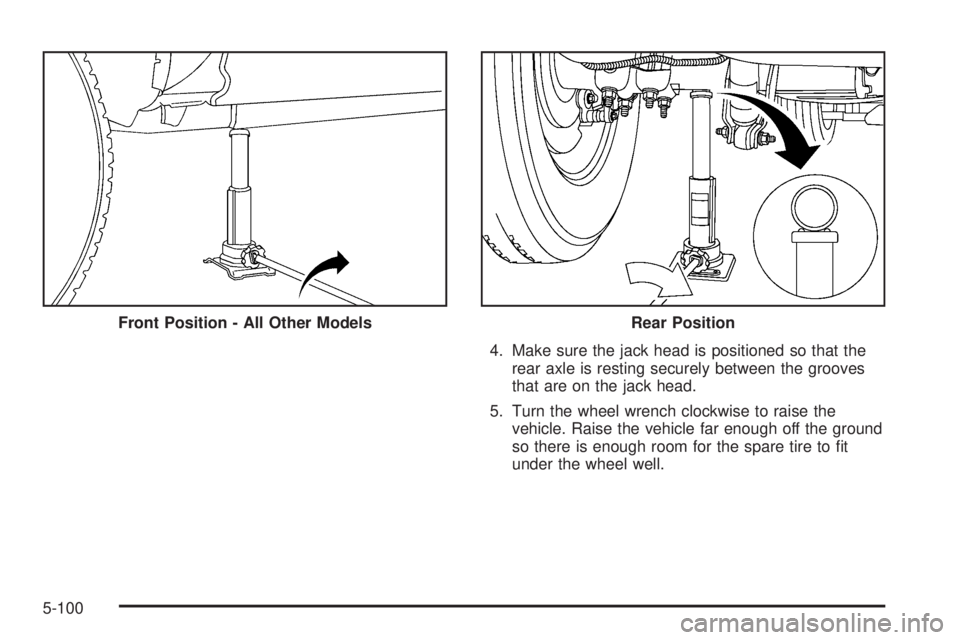
4. Make sure the jack head is positioned so that the
rear axle is resting securely between the grooves
that are on the jack head.
5. Turn the wheel wrench clockwise to raise the
vehicle. Raise the vehicle far enough off the ground
so there is enough room for the spare tire to t
under the wheel well. Front Position - All Other Models
Rear Position
5-100
Page 513 of 600
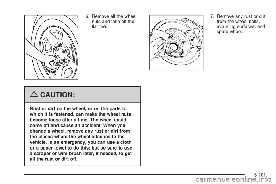
6. Remove all the wheel
nuts and take off the
at tire.
{CAUTION:
Rust or dirt on the wheel, or on the parts to
which it is fastened, can make the wheel nuts
become loose after a time. The wheel could
come off and cause an accident. When you
change a wheel, remove any rust or dirt from
the places where the wheel attaches to the
vehicle. In an emergency, you can use a cloth
or a paper towel to do this; but be sure to use
a scraper or wire brush later, if needed, to get
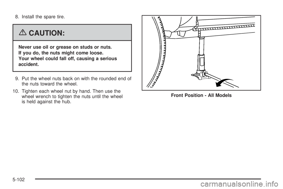
all the rust or dirt off.7. Remove any rust or dirt
from the wheel bolts,
mounting surfaces, and
spare wheel.
5-101
Page 514 of 600
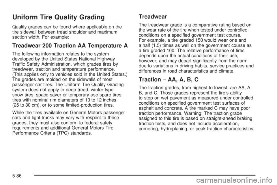
8. Install the spare tire.
{CAUTION:
Never use oil or grease on studs or nuts.
If you do, the nuts might come loose.
Your wheel could fall off, causing a serious
accident.
9. Put the wheel nuts back on with the rounded end of
the nuts toward the wheel.
10. Tighten each wheel nut by hand. Then use the
wheel wrench to tighten the nuts until the wheel
is held against the hub.Front Position - All Models
5-102