Page 443 of 524
12. Turn the wheel wrench counterclockwise to lower
the spare the rest of the way.13. Tilt the retainer at the end of the cable and pull it
through the wheel opening. Pull the tire out from
under the vehicle.
Notice:If you drive away before the spare tire or
secondary latch system cable has been reinstalled,
you could damage your vehicle. Always reinstall
this cable before driving your vehicle.
14. Turn the wheel wrench clockwise to raise the cable
back up if the cable is hanging under the vehicle.
Have the hoist assembly inspected as soon as you can.
You will not be able to store a spare tire using the
hoist assembly until it has been repaired or replaced.
5-87
Page 445 of 524

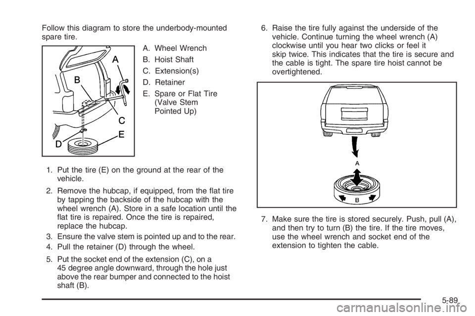
Follow this diagram to store the underbody-mounted
spare tire.
A. Wheel Wrench
B. Hoist Shaft
C. Extension(s)
D. Retainer
E. Spare or Flat Tire
(Valve Stem
Pointed Up)
1. Put the tire (E) on the ground at the rear of the
vehicle.
2. Remove the hubcap, if equipped, from the �at tire
by tapping the backside of the hubcap with the
wheel wrench (A). Store in a safe location until the
�at tire is repaired. Once the tire is repaired,
replace the hubcap.
3. Ensure the valve stem is pointed up and to the rear.
4. Pull the retainer (D) through the wheel.
5. Put the socket end of the extension (C), on a
45 degree angle downward, through the hole just
above the rear bumper and connected to the hoist
shaft (B).6. Raise the tire fully against the underside of the
vehicle. Continue turning the wheel wrench (A)
clockwise until you hear two clicks or feel it
skip twice. This indicates that the tire is secure and
the cable is tight. The spare tire hoist cannot be
overtightened.
7. Make sure the tire is stored securely. Push, pull (A),
and then try to turn (B) the tire. If the tire moves,
use the wheel wrench and socket end of the
extension to tighten the cable.
5-89
Page 446 of 524
8. Return the equipment to the proper location in the
vehicle as shown next.
A. Handle
B. Wheel Wrench
C. Instruction Label
D. Extension(s)E. Knob
F. Wheel Blocks
and Jack1. Attach the handle (A), wheel wrench (B), and
extension (D) in the slots provided.
2. Roll up the instruction label (C) and return to the
slot in the tool kit.
3. Assemble the wheel blocks (F) to the jack.
4. Turn the knob (E) on the jack clockwise to raise the
jack head.
5. Return the rear seat to its proper position.
Regular Model
5-90
Page 447 of 524
A. Instruction Label
B. Handle
C. Knob
D. Extension(s)E. Wheel Blocks
and Jack
F. Wheel Wrench1. Roll up the instruction label (A) and return to the
slot in the tool kit.
2. Insert the handle (B) and wheel wrench (F) in the
slots provided.
3. Insert the wheel blocks (E) and then the jack (E).
4. Turn the knob (C) on the jack clockwise to raise the
jack head.
5. Reinstall the cover.
Extended Model
5-91