Page 12 of 312
WARNING LIGHTS AND CHIMES
Standard instrument cluster (manual transmission)
Standard instrument cluster (automatic transmission)
Amarillo instrument cluster
Warning lights and gauges can alert you to a vehicle condition that may
become serious enough to cause expensive repairs. A warning light may
illuminate when a problem exists with one of your vehicle’s functions.
2006 F-250/350/450/550(f23)
Owners Guide (post-2002-fmt)
USA(fus)
Instrument Cluster
12
Page 19 of 312

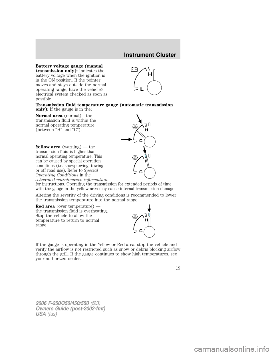
Battery voltage gauge (manual
transmission only):Indicates the
battery voltage when the ignition is
in the ON position. If the pointer
moves and stays outside the normal
operating range, have the vehicle’s
electrical system checked as soon as
possible.
Transmission fluid temperature gauge (automatic transmission
only):If the gauge is in the:
Normal area(normal) - the
transmission fluid is within the
normal operating temperature
(between “H” and “C”).
Yellow area(warning) —
the
transmission fluid is higher than
normal operating temperature. This
can be caused by special operation
conditions (i.e. snowplowing, towing
or off road use). Refer toSpecial
Operating Conditionsin the
scheduled maintenance information
for instructions. Operating the transmission for extended periods of time
with the gauge in the yellow area may cause internal transmission damage.
Altering the severity of the driving conditions is recommended to lower
the transmission temperature into the normal range.
Red area(over temperature) —
the transmission fluid is overheating.
Stop the vehicle to allow the
temperature to return to normal
range.
If the gauge is operating in the Yellow or Red area, stop the vehicle and
verify the airflow is not restricted such as snow or debris blocking airflow
through the grill. If the gauge continues to show high temperatures, see
your authorized dealer.
2006 F-250/350/450/550(f23)
Owners Guide (post-2002-fmt)
USA(fus)
Instrument Cluster
19
Page 154 of 312

components carefully prior to and after any towing operation. Refer to
Transmission temperature gaugein theInstrument Clusterchapter
for the transmission fluid temperature information.
The following trailer towing charts apply to vehicles equipped with
gasoline engines; for vehicles equipped with diesel engines, refer to your
6.0 Liter Power Stroke Direct Injection Turbo Diesel Owner’s Guide
Supplement.
Note:Do not exceed the GCWR listed for your vehicle on the following
chart/table, or the GVWR, GAWR or tire ratings specified on the Tire
Label or Safety Compliance Certification Label.
Towing trailers beyond the maximum recommended trailer
weight which exceeds the limit of the vehicle’s GCWR, GVWR,
GAWR or tire ratings could result in engine damage, transmission
damage, structural damage, loss of vehicle control, vehicle rollover and
personal injury.
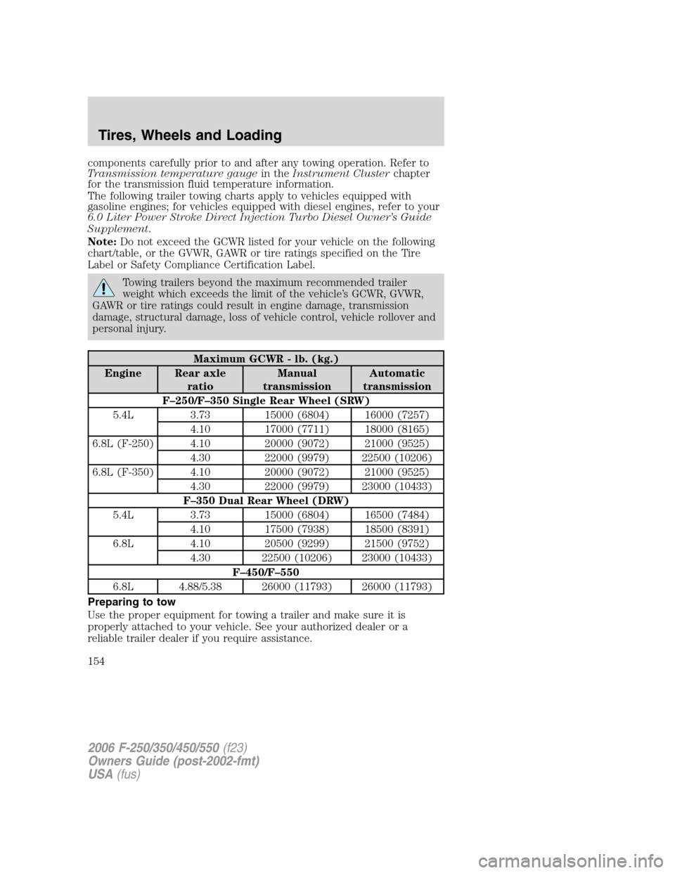
Maximum GCWR - lb. (kg.)
Engine Rear axle
ratioManual
transmissionAutomatic
transmission
F–250/F–350 Single Rear Wheel (SRW)
5.4L 3.73 15000 (6804) 16000 (7257)
4.10 17000 (7711) 18000 (8165)
6.8L (F-250) 4.10 20000 (9072) 21000 (9525)
4.30 22000 (9979) 22500 (10206)
6.8L (F-350) 4.10 20000 (9072) 21000 (9525)
4.30 22000 (9979) 23000 (10433)
F–350 Dual Rear Wheel (DRW)
5.4L 3.73 15000 (6804) 16500 (7484)
4.10 17500 (7938) 18500 (8391)
6.8L 4.10 20500 (9299) 21500 (9752)
4.30 22500 (10206) 23000 (10433)
F–450/F–550
6.8L 4.88/5.38 26000 (11793) 26000 (11793)
Preparing to tow
Use the proper equipment for towing a trailer and make sure it is
properly attached to your vehicle. See your authorized dealer or a
reliable trailer dealer if you require assistance.
2006 F-250/350/450/550(f23)
Owners Guide (post-2002-fmt)
USA(fus)
Tires, Wheels and Loading
154
Page 164 of 312
4x4 with manual shift transfer case:
•Place the transfer case in N (Neutral).
•Front hub locks are in the FREE position.
4x4 electronic shift transfer case vehicles with automatic
transmissions:
Regarding recreational towing or having your vehicle towed, 4x4 vehicles
with electronic shift on the fly cannot be towed with any wheels on the
ground unless the rear driveshaft is removed and the front hub locks are
in the AUTO position (with the exception of moving it as a disabled
vehicle off the road out of traffic).
2006 F-250/350/450/550(f23)
Owners Guide (post-2002-fmt)
USA(fus)
Tires, Wheels and Loading
164
Page 165 of 312

STARTING
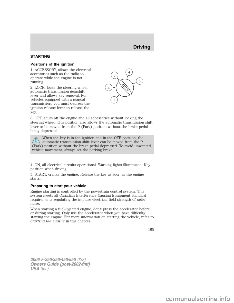
Positions of the ignition
1. ACCESSORY, allows the electrical
accessories such as the radio to
operate while the engine is not
running.
2. LOCK, locks the steering wheel,
automatic transmission gearshift
lever and allows key removal. For
vehicles equipped with a manual
transmission, you must depress the
ignition release lever to release the
key.
3. OFF, shuts off the engine and all accessories without locking the
steering wheel. This position also allows the automatic transmission shift
lever to be moved from the P (Park) position without the brake pedal
being depressed.
When the key is in the ignition and in the OFF position, the
automatic transmission shift lever can be moved from the P
(Park) position without the brake pedal depressed. To avoid unwanted
vehicle movement, always set the parking brake.
4. ON, all electrical circuits operational. Warning lights illuminated. Key
position when driving.
5. START, cranks the engine. Release the key as soon as the engine
starts.
Preparing to start your vehicle
Engine starting is controlled by the powertrain control system. This
system meets all Canadian Interference-Causing Equipment standard
requirements regulating the impulse electrical field strength of radio
noise.
When starting a fuel-injected engine, don’t press the accelerator before
or during starting. Only use the accelerator when you have difficulty
starting the engine. For more information on starting the vehicle, refer to
Starting the enginein this chapter.
3
1
2
5
4
2006 F-250/350/450/550(f23)
Owners Guide (post-2002-fmt)
USA(fus)
Driving
165
Page 167 of 312
If starting a vehicle with an automatic transmission:
1. Make sure the parking brake is
set.
2. Make sure the gearshift is in P
(Park).
If starting a vehicle with a manual
transmission:
1. Make sure the parking brake is
set.
2. Push the clutch pedal to the floor.
2006 F-250/350/450/550(f23)
Owners Guide (post-2002-fmt)
USA(fus)
Driving
167
Page 172 of 312
Parking brake
To set the parking brake, press the
parking brake pedal down until the
pedal stops.
The BRAKE warning lamp in the
instrument cluster illuminates and
remains illuminated until the
parking brake is released.
Pull the right side of the release
lever to release the parking brake;
the release lever pulls at an angle
toward the driver’s door. To prevent
the pedal from releasing too quickly,
place your left foot on the parking
brake pedal, then pull the release
lever, making sure the pedal fully
releases. You may want to pull the
release lever again to make sure the
parking brake is full released.
Always set the parking brake fully and make sure that the
gearshift is securely latched in P (Park) (automatic
transmission) or in 1 (First) (manual transmission).
P!
BRAKE
2006 F-250/350/450/550(f23)
Owners Guide (post-2002-fmt)
USA(fus)
Driving
172
Page 173 of 312

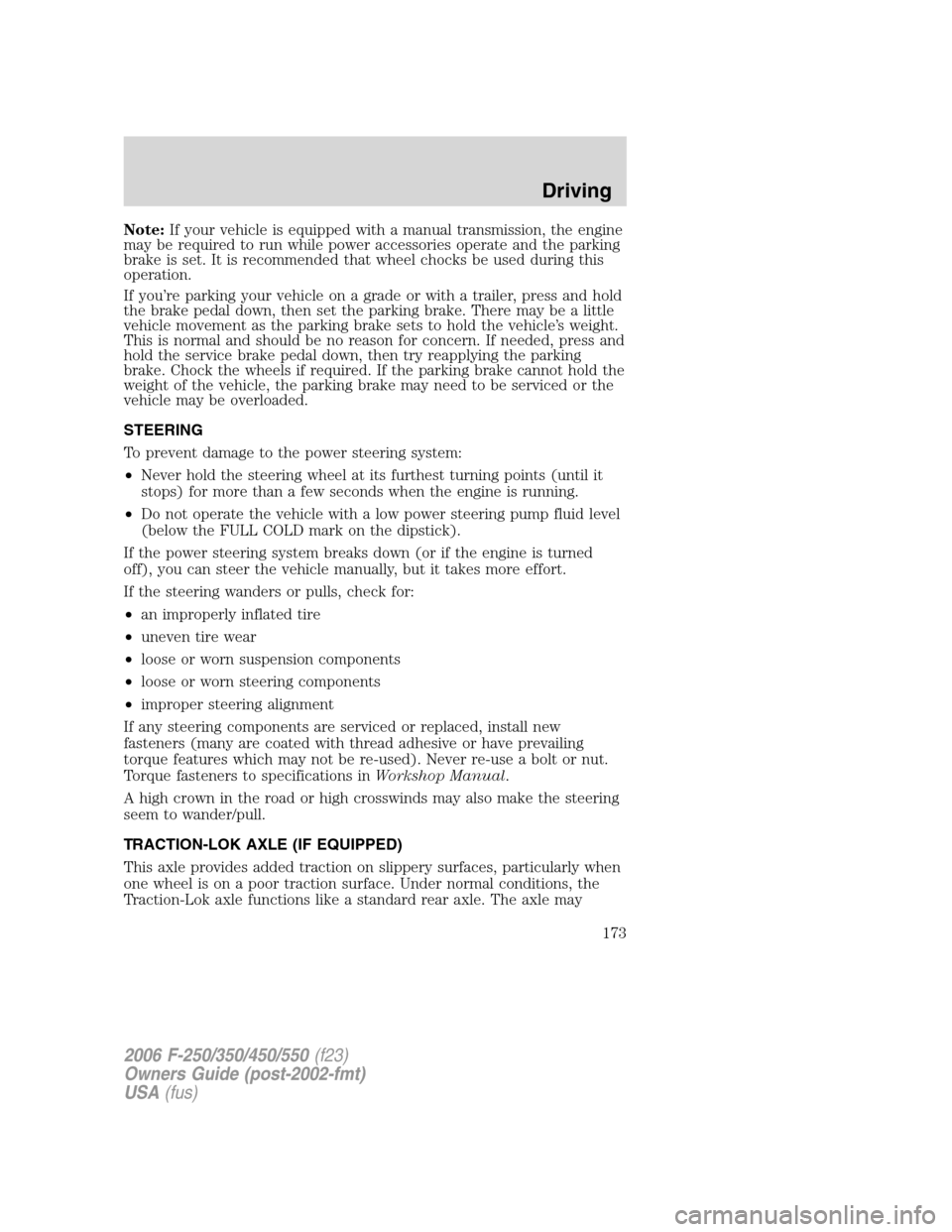
Note:If your vehicle is equipped with a manual transmission, the engine
may be required to run while power accessories operate and the parking
brake is set. It is recommended that wheel chocks be used during this
operation.
If you’re parking your vehicle on a grade or with a trailer, press and hold
the brake pedal down, then set the parking brake. There may be a little
vehicle movement as the parking brake sets to hold the vehicle’s weight.
This is normal and should be no reason for concern. If needed, press and
hold the service brake pedal down, then try reapplying the parking
brake. Chock the wheels if required. If the parking brake cannot hold the
weight of the vehicle, the parking brake may need to be serviced or the
vehicle may be overloaded.
STEERING
To prevent damage to the power steering system:
•Never hold the steering wheel at its furthest turning points (until it
stops) for more than a few seconds when the engine is running.
•Do not operate the vehicle with a low power steering pump fluid level
(below the FULL COLD mark on the dipstick).
If the power steering system breaks down (or if the engine is turned
off), you can steer the vehicle manually, but it takes more effort.
If the steering wanders or pulls, check for:
•an improperly inflated tire
•uneven tire wear
•loose or worn suspension components
•loose or worn steering components
•improper steering alignment
If any steering components are serviced or replaced, install new
fasteners (many are coated with thread adhesive or have prevailing
torque features which may not be re-used). Never re-use a bolt or nut.
Torque fasteners to specifications inWorkshop Manual.
A high crown in the road or high crosswinds may also make the steering
seem to wander/pull.
TRACTION-LOK AXLE (IF EQUIPPED)
This axle provides added traction on slippery surfaces, particularly when
one wheel is on a poor traction surface. Under normal conditions, the
Traction-Lok axle functions like a standard rear axle. The axle may
2006 F-250/350/450/550(f23)
Owners Guide (post-2002-fmt)
USA(fus)
Driving
173