Page 159 of 248

Do not rock the vehicle if the engine is not at normal operating
temperature or damage to the transmission may occur.
Do not rock the vehicle for more than a minute or damage to the
transmission and tires may occur, or the engine may overheat.
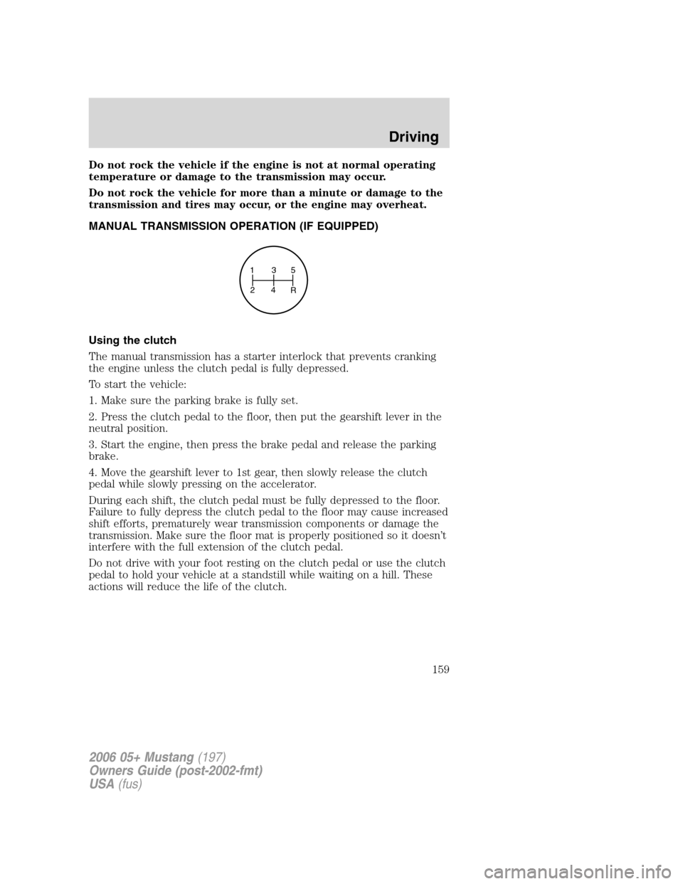
MANUAL TRANSMISSION OPERATION (IF EQUIPPED)
Using the clutch
The manual transmission has a starter interlock that prevents cranking
the engine unless the clutch pedal is fully depressed.
To start the vehicle:
1. Make sure the parking brake is fully set.
2. Press the clutch pedal to the floor, then put the gearshift lever in the
neutral position.
3. Start the engine, then press the brake pedal and release the parking
brake.
4. Move the gearshift lever to 1st gear, then slowly release the clutch
pedal while slowly pressing on the accelerator.
During each shift, the clutch pedal must be fully depressed to the floor.
Failure to fully depress the clutch pedal to the floor may cause increased
shift efforts, prematurely wear transmission components or damage the
transmission. Make sure the floor mat is properly positioned so it doesn’t
interfere with the full extension of the clutch pedal.
Do not drive with your foot resting on the clutch pedal or use the clutch
pedal to hold your vehicle at a standstill while waiting on a hill. These
actions will reduce the life of the clutch.
135
24
R
2006 05+ Mustang(197)
Owners Guide (post-2002-fmt)
USA(fus)
Driving
159
Page 161 of 248
DRIVING THROUGH WATER
If driving through deep or standing
water is unavoidable, proceed very
slowly especially when the depth is
not known. Never drive through
water that is higher than the bottom
of the wheel rims (for cars) or the
bottom of the hubs (for trucks).
When driving through water, traction or brake capability may be limited.
Also, water may enter your engine’s air intake and severely damage your
engine or your vehicle may stall.Driving through deep water where
the transmission vent tube is submerged may allow water into the
transmission and cause internal transmission damage.
Once through the water, always dry the brakes by moving your
vehicle slowly while applying light pressure on the brake pedal.
Wet brakes do not stop the vehicle as quickly as dry brakes.
2006 05+ Mustang(197)
Owners Guide (post-2002-fmt)
USA(fus)
Driving
161
Page 164 of 248

Note:With extended use, the flasher may run down your battery.
FUEL PUMP SHUT-OFF SWITCH
FUEL
RESET
This device stops the electric fuel pump from sending fuel to the engine
when your vehicle has had a substantial jolt.
After an accident, if the engine cranks but does not start, this switch
may have been activated.
The fuel pump shut-off switch is
located in the driver’s footwell, by
the hood release
To reset the switch:
1. Turn the ignition OFF.
2. Check the fuel system for leaks.
3. If no leaks are apparent, reset the
switch by pushing in on the reset
button.
4. Turn the ignition ON.
5. Wait a few seconds and return the key to OFF.
6. Make another check for leaks.
FUSES AND RELAYS
Fuses
If electrical components in the
vehicle are not working, a fuse may
have blown. Blown fuses are
identified by a broken wire within
the fuse. Check the appropriate
fuses before replacing any electrical
components.
Note:Always replace a fuse with one that has the specified amperage
rating. Using a fuse with a higher amperage rating can cause severe wire
damage and could start a fire.
15
2006 05+ Mustang(197)
Owners Guide (post-2002-fmt)
USA(fus)
Roadside Emergencies
164
Page 167 of 248

Fuse/Relay
LocationFuse Amp
RatingPassenger Compartment Fuse
Panel Description
17 10A Restraint Control Module (RCM),
Passenger Occupant Detection
System (PODS), Passenger Air
bag Deactivation Indicator (PADI)
18 10A Anti-lock Brake System (ABS),
Positive Crankcase Ventilation
(PCV) valve heater, Ignition
19 5A Powertrain Control Module (PCM)
relays, Passive Anti-Theft System
(PATS)
20 10A Radio (Start)
21 10A Starter relay
Power distribution box
The power distribution box is located in the engine compartment. The
power distribution box contains high-current fuses that protect your
vehicle’s main electrical systems from overloads.
Do not probe the contacts for the fuses and relays in the power
distribution box as damage will occur, causing improper, or loss
of, electrical functionality.
Always disconnect the battery before servicing high current
fuses.
To reduce risk of electrical shock, always replace the cover to
the Power Distribution Box before reconnecting the battery or
refilling fluid reservoirs.
If the battery has been disconnected and reconnected, refer to the
Batterysection of theMaintenance and Specificationschapter.
2006 05+ Mustang(197)
Owners Guide (post-2002-fmt)
USA(fus)
Roadside Emergencies
167
Page 169 of 248
Fuse/Relay
LocationFuse Amp
RatingPower Distribution Box
Description
13 40A* Convertible top
14 30A* Seat
15 — Not used
16 30A* Front amplifier (Shaker 500
radio)
20 Mini relay PCM #2
21 Micro relay Fuel pump
22 Mini relay Starter
23 Micro relay PCM #1
24 Micro relay A/C clutch
25 Mini relay Cooling fan (High-speed)
26 Mini relay Horn
27 Micro relay High beams
28 Mini relay Cooling fan (Low-speed)
29 Mini relay Rear defroster
30 Micro relay Fog lamps
31 Mini relay Convertible top (Up)
32 Mini relay Climate control blower
33 Mini relay Convertible top (Down)
34 Micro relay Decklid
35 — Not used
36 — Not used
37 — Not used
38 — Not used
39 — Not used
40 15A** Engine #2
41 15A** Fuel pump
42 15A** Engine #3
43 10A** Alternator
44 10A** Delayed accessory
45 10A** PCM
2006 05+ Mustang(197)
Owners Guide (post-2002-fmt)
USA(fus)
Roadside Emergencies
169
Page 170 of 248
Fuse/Relay
LocationFuse Amp
RatingPower Distribution Box
Description
46 25A** Horn
47 15A** Engine #1
48 Diode A/C clutch
49 15A** A/C clutch
50 15A** High beams
51 10A** Convertible top
52 30A** Rear defroster
53 Diode PCM
54 10A** PCM delay
55 — Not used
56 20A** Radio
57 20A** Decklid release
58 15A** Fog lamps
59 30A** SJB #5 (Instrument panel fuse
box)
60 — Not used
61 20A** Power point #1 (Instrument
panel)
62 20A** SJB #7 (Instrument panel fuse
box)
63 30A** SJB #6 (Instrument panel fuse
box)
64 20A** Power point #2 (Console)
65 30A** ABS #2
66 — Not used
67 30A** SJB #4 (Instrument panel fuse
box)
68 20A** Ignition
* Cartridge Fuses ** Mini Fuses
Auxiliary relay
There is a relay located on the accelerator pedal assembly for the PCM
delay. Note: Only on manual transmission applications.
2006 05+ Mustang(197)
Owners Guide (post-2002-fmt)
USA(fus)
Roadside Emergencies
170
Page 175 of 248

4. Put the jack in the jack notch
next to the tire you are changing.
Turn the jack handle clockwise until
the wheel is completely off the
ground.
Never use the rear differential
as a jacking point.
To lessen the risk of
personal injury, do not put
any part of your body under the
vehicle while changing a tire. Do
not start the engine when your
vehicle is on the jack. The jack is
only meant for changing the tire.
5. Remove the lug nuts with the lug wrench.
6. Replace the flat tire with the spare tire, making sure the valve stem is
facing outward. Reinstall lug nuts until the wheel is snug against the hub.
Do not fully tighten the lug nuts until the wheel has been lowered.
If you are using the temporary tire, the lug nut washers will not appear
to be flush with the rim. This is normal only when using the temporary
spare tire.
7. Lower the wheel by turning the jack handle counterclockwise.
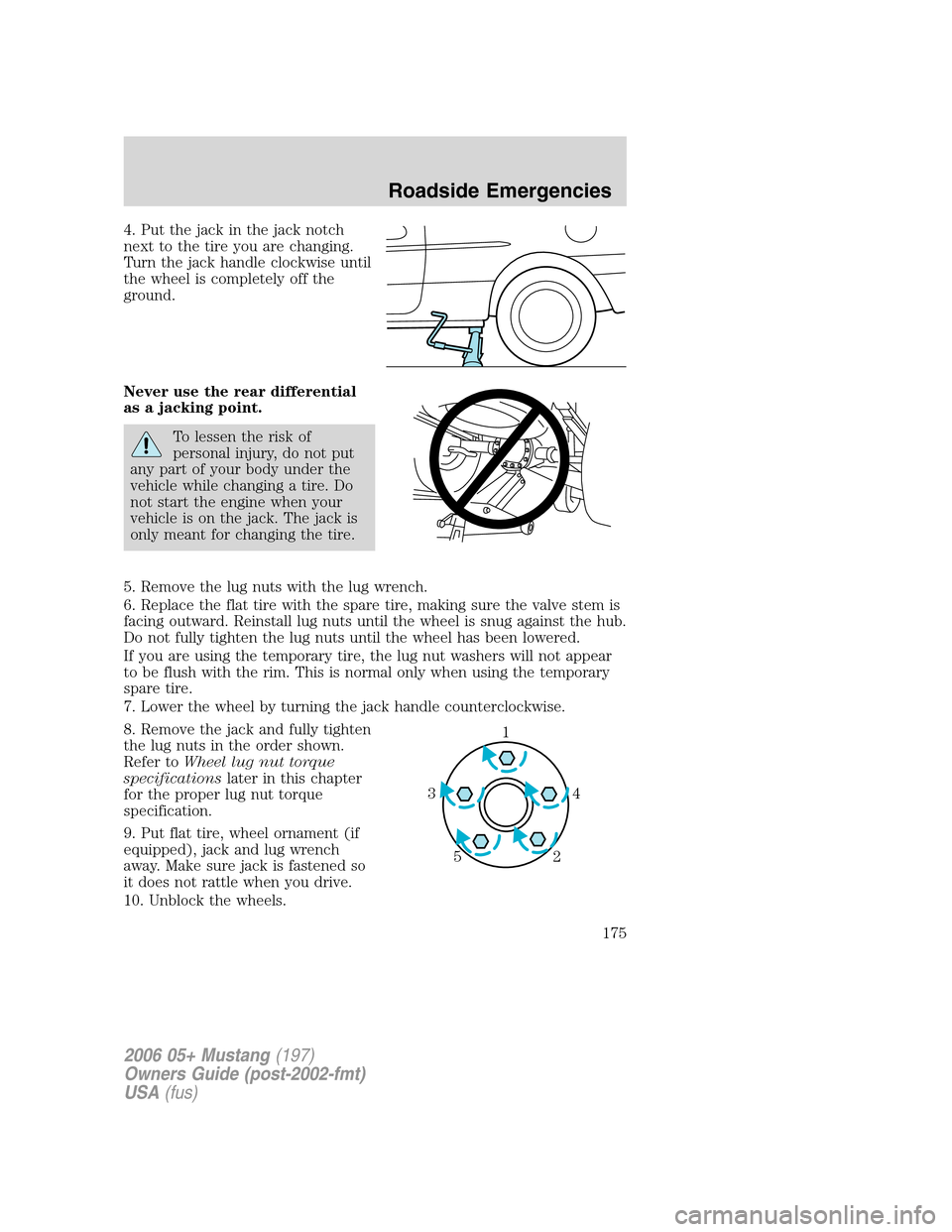
8. Remove the jack and fully tighten
the lug nuts in the order shown.
Refer toWheel lug nut torque
specificationslater in this chapter
for the proper lug nut torque
specification.
9. Put flat tire, wheel ornament (if
equipped), jack and lug wrench
away. Make sure jack is fastened so
it does not rattle when you drive.
10. Unblock the wheels.
1
4 3
2 5
2006 05+ Mustang(197)
Owners Guide (post-2002-fmt)
USA(fus)
Roadside Emergencies
175
Page 177 of 248
1.Use only a 12–volt supply to start your vehicle.
2. Do not disconnect the battery of the disabled vehicle as this could
damage the vehicle’s electrical system.
3. Park the booster vehicle close to the hood of the disabled vehicle
making sure the two vehiclesdo nottouch. Set the parking brake on
both vehicles and stay clear of the engine cooling fan and other moving
parts.
4. Check all battery terminals and remove any excessive corrosion before
you attach the battery cables. Ensure the vent caps are tight and level.
5. Turn the heater fan on in both vehicles to protect any electrical
surges. Turn all other accessories off.
Connecting the jumper cables
1. Connect the positive (+) jumper cable to the positive (+) terminal of
the discharged battery.
Note:In the illustrations,lightning boltsare used to designate the
assisting (boosting) battery.
+–+–
+–+–
2006 05+ Mustang(197)
Owners Guide (post-2002-fmt)
USA(fus)
Roadside Emergencies
177