Page 102 of 198

Downloaded from www.Manualslib.com manuals search engine GENERAL INFORMATION
General points on starting
If the battery has been disconnectedthe vehicle may exhibit some unusualdriving characteristics for approx. 8kilometres (5 miles) afterreconnecting the battery.
This is because the enginemanagement system must realignitself with the engine. Any unusualdriving characteristics during thisperiod may be disregarded.
Starting the engine bytowing or pushing
WARNING
To prevent damage you mustnot push or tow start yourvehicle. Use booster cables and abooster battery. See Using boostercables (page 158).
IGNITION SWITCH
Ignition switch positions
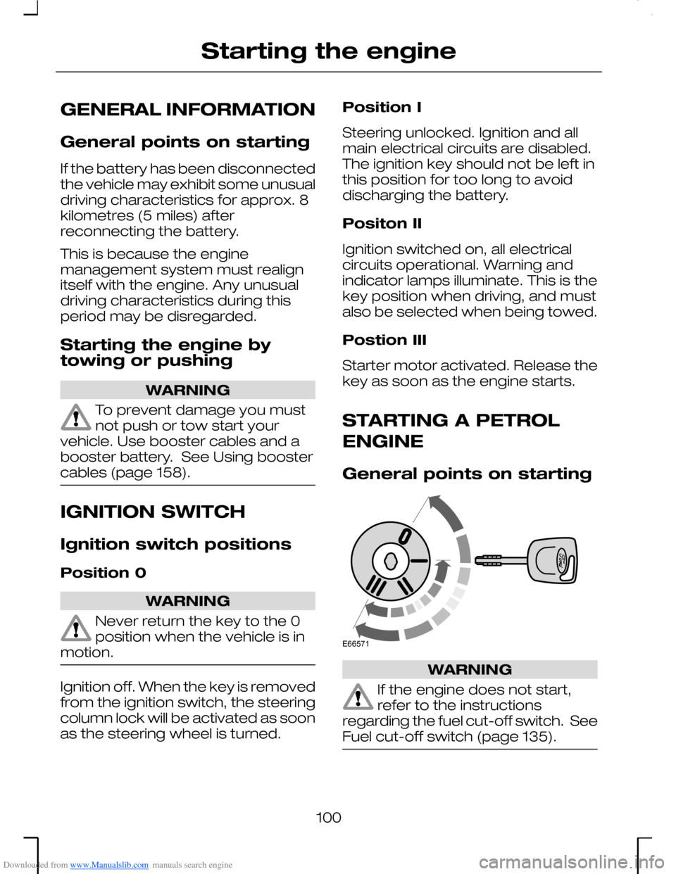
Position 0
WARNING
Never return the key to the 0position when the vehicle is inmotion.
Ignition off. When the key is removedfrom the ignition switch, the steeringcolumn lock will be activated as soonas the steering wheel is turned.
Position I
Steering unlocked. Ignition and allmain electrical circuits are disabled.The ignition key should not be left inthis position for too long to avoiddischarging the battery.
Positon II
Ignition switched on, all electricalcircuits operational. Warning andindicator lamps illuminate. This is thekey position when driving, and mustalso be selected when being towed.
Postion III
Starter motor activated. Release thekey as soon as the engine starts.
STARTING A PETROL
ENGINE
General points on starting
WARNING
If the engine does not start,refer to the instructionsregarding the fuel cut-off switch. SeeFuel cut-off switch (page 135).
100
Starting the engineE66571
Page 118 of 198

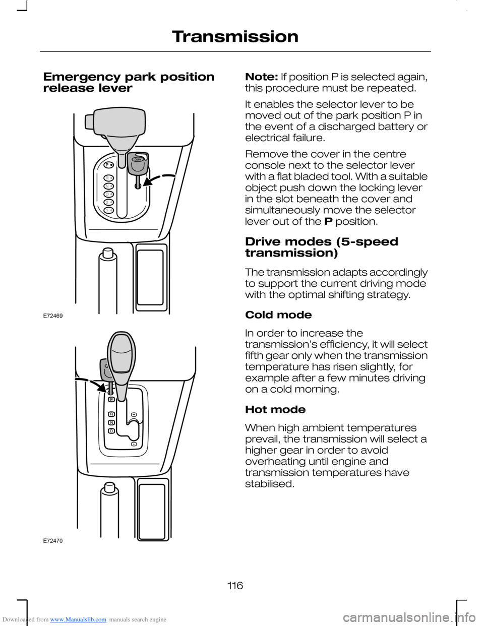
Downloaded from www.Manualslib.com manuals search engine Emergency park positionrelease lever
Note: If position P is selected again,this procedure must be repeated.
It enables the selector lever to bemoved out of the park position P inthe event of a discharged battery orelectrical failure.
Remove the cover in the centreconsole next to the selector leverwith a flat bladed tool. With a suitableobject push down the locking leverin the slot beneath the cover andsimultaneously move the selectorlever out of the P position.
Drive modes (5-speedtransmission)
The transmission adapts accordinglyto support the current driving modewith the optimal shifting strategy.
Cold mode
In order to increase thetransmission’s efficiency, it will selectfifth gear only when the transmissiontemperature has risen slightly, forexample after a few minutes drivingon a cold morning.
Hot mode
When high ambient temperaturesprevail, the transmission will select ahigher gear in order to avoidoverheating until engine andtransmission temperatures havestabilised.
116
TransmissionE72469 E72470
Page 138 of 198
Downloaded from www.Manualslib.com manuals search engine FUSE BOX LOCATIONS
WARNING
Any improper alterations to theelectrical or fuel system canendanger the safety of the vehicle asthey could constitute a fire hazard orcause engine damage. Have anywork involving these systems or thereplacement of relays or high currentcarrying fuses carried out by anexpert.
Auxiliary fuse boxA
Central fuse boxB
Auxiliary fuse box
To check or replace a fuse, first pulloff the battery cover 1. Then removethe cover of the fuse box 2 byreleasing the catch and lifting up.
You will find the fuse chart inside thefuse box cover.
Central fuse box
Left-hand drive
136
FusesE72532 E72534 E72535
Page 140 of 198
Downloaded from www.Manualslib.com manuals search engine Auxiliary fuse box
Circuits protectedFuse
Conventional headlamps: 7.5 A; Xenon headlamps: 20 A16/18
Automatic transmission: 10 A17
Auxiliary heater (Diesel): 20 A; Battery Backed−up Sounder (ST):7.5 A23
Diode electronic module34
Diode air conditioning35
Diode engine cooling fan36
HO2S sensor37
Engine Control Valves/Vehicle Speed Sensor40
Engine management Duratec engines: 10 A; Duratorq engines:15 A42
Central fuse box
Circuits protectedFuse
Audio system or audio system and instrument cluster69
Trailer – max. 20 A fuse74
Instrument cluster78
Reversing lamps80
Sensors for passenger airbag and automatic climate control81
Daytime running lamps88
Trailer – max. 20 A fuse92
Brake lamps93
License plate lamps97
Symbols in the fuse box
See Owner’s handbook
Airbag
ABS
Dipped beam
Main beam or headlamps
138
Fuses
Page 142 of 198
Downloaded from www.Manualslib.com manuals search engine Ignition, ignition switch
Fuel pump
Auxiliary or fuel fired heater,glow plugs (diesel), fuelinjection pump relay (diesel)
Battery sensing
Engine cooling fan
Automatic transmission
Auxiliary power sockets
Battery positive feed
Diode
140
Fuses
Page 147 of 198
Downloaded from www.Manualslib.com manuals search engine ENGINE COMPARTMENT OVERVIEW
Duratec-HE/SCi
Engine coolant reservoirA
Power steering fluid reservoirB
Engine oil filler cap*C
Brake/clutch fluid reservoirD
Air cleanerE
Auxiliary fuse boxF
BatteryG
Engine oil dipstick*H
Washer fluid reservoirI
* For easy identification, filler caps and the engine oil dipstick are marked incolour.
145
MaintenanceE73408
Page 148 of 198
Downloaded from www.Manualslib.com manuals search engine Duratec-VE
Engine coolant reservoirA
Power steering fluid reservoirB
Engine oil filler cap*C
Brake/clutch fluid reservoirD
Air cleanerE
Auxiliary fuse boxF
BatteryG
Engine oil dipstick*H
Washer fluid reservoirI
* For easy identification, filler caps and the engine oil dipstick are marked incolour.
146
MaintenanceE73409
Page 149 of 198
Downloaded from www.Manualslib.com manuals search engine Duratec-VE/ST V6
Engine coolant reservoirA
Power steering fluid reservoirB
Engine oil filler cap*C
Brake/clutch fluid reservoirD
Air cleanerE
Auxiliary fuse boxF
BatteryG
Engine oil dipstick*H
Washer fluid reservoirI
* For easy identification, filler caps and the engine oil dipstick are marked incolour.
147
MaintenanceE73410