Page 209 of 312
Fuse/Relay
Location Fuse Amp
Rating Passenger Compartment Fuse
Panel Description
15 — Not used
16 — Not used
17 15A* Exterior lamps
18 20A* Flasher, Brake On-Off (BOO)
lamps
19 10A* Body Security Module (BSM)
(Security)
20 15A* Trailer tow Electric Brake
Controller (EBC)
21 20A* Heated seats
22 20A* Engine control
23 20A* Engine control (gasoline engine
only)/Climate control (Diesel
engine only)
24 15A* Tow haul, Blower relay, Electronic
Automatic Temperature Control
(EATC)
25 — Not used
26 10A* Airbags
27 15A* Ignition switch RUN feed
28 10A* Trailer tow EBC logic
29 10A* Customer access
30 15A* High beam headlamps
31 15A* Starter relay
32 5A* Radio (start)
33 15A* Cluster, 4x4, Wipers
34 10A* BOO switch (Low current)
35 10A* Instrument cluster
36 — Not used
37 15A* Horn
38 20A* Trailer tow park lamps
39 15A* Heated mirrors
2006 F-250/350/450/550 (f23)
Owners Guide (post-2002-fmt)
USA (fus) Roadside Emergencies
209
Page 211 of 312
Fuse/Relay
Location Fuse Amp
Rating Passenger Compartment Fuse
Panel Description
304 — Not used
305 Full ISO relay Upfitter control
306 Full ISO relay Delayed accessory
307 Full ISO relay Starter
601 30A circuit
breaker Delayed accessory, Power
windows, Moonroof
602 — Not used
* Mini fuse ** Cartridge fuse
Power distribution box
The power distribution box is located in the engine compartment. The
power distribution box contains high-current fuses that protect your
vehicle’s main electrical systems from overloads.
Always disconnect the battery before servicing high current
fuses.
To reduce risk of electrical shock, always replace the cover to
the Power Distribution Box before reconnecting the battery or
refilling fluid reservoirs.
If the battery has been disconnected and reconnected, refer to the
Battery section of the Maintenance and Specifications chapter.
2006 F-250/350/450/550 (f23)
Owners Guide (post-2002-fmt)
USA (fus) Roadside Emergencies
211
Page 212 of 312
The high-current fuses and relays are coded as follows.
Fuse/Relay
Location Fuse Amp
Rating Power Distribution Box
Description
1 30A* Wipers
2 40A* Blower
3 30A* Electronic Shift on the Fly
(ESOF)
4 — Not used
5 50A* Injector Driver Module (IDM)
(Diesel engine only)
6 — Not used
7 30A* Horizontal Fuel Conditioner
Module (HFCM) (Diesel engine
only)
8 — Shunt
9 20A** Trailer tow turn signals
10 10A** Powertrain Control Module (PCM)
keep alive power, Canister vent
solenoid (gasoline engine only)
11 10A** Anti-lock Brake System (ABS)
2006 F-250/350/450/550 (f23)
Owners Guide (post-2002-fmt)
USA (fus)Roadside Emergencies
212
Page 213 of 312
Fuse/Relay
Location Fuse Amp
Rating Power Distribution Box
Description
12 2A** Brake pressure switch
13 15A** Daytime Running Lamps (DRL)
14 — Not used
15 15A** IDM logic (Diesel engine only)
16 — Not used
17 10A** A/C clutch
18 10A** IDM relay (Diesel engine only)
19 — Not used
20 10A** Trailer tow back-up lamps
21 — Not used
22 60A*** ABS (Coils)
23 60A*** ABS (Pump)
201 1
� 2
ISO relay Trailer tow right turn signal/stop
lamp
202 1
� 2
ISO relay Trailer tow left turn signal/stop
lamp
203 1
� 2
ISO relay A/C clutch
204 — Not used
205 1
� 2
ISO relay DRL #1
206 1
� 2
ISO relay DRL #2
301 Full ISO relay DRL #3
302 Full ISO relay HFCM
303 Full ISO relay Blower
304 High-current
relay IDM (Diesel engine only)
* Cartridge Fuse ** Mini Fuses *** Maxi fuse
2006 F-250/350/450/550 (f23)
Owners Guide (post-2002-fmt)
USA (fus) Roadside Emergencies
213
Page 214 of 312

Relays
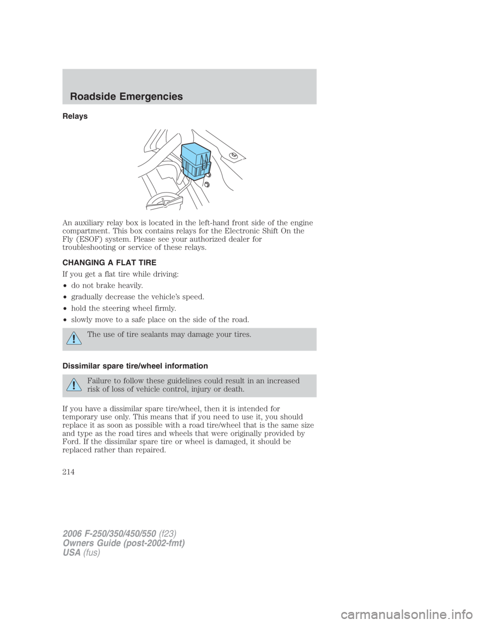
An auxiliary relay box is located in the left-hand front side of the engine
compartment. This box contains relays for the Electronic Shift On the
Fly (ESOF) system. Please see your authorized dealer for
troubleshooting or service of these relays.
CHANGING A FLAT TIRE
If you get a flat tire while driving:
• do not brake heavily.
• gradually decrease the vehicle’s speed.
• hold the steering wheel firmly.
• slowly move to a safe place on the side of the road.
The use of tire sealants may damage your tires.
Dissimilar spare tire/wheel information
Failure to follow these guidelines could result in an increased
risk of loss of vehicle control, injury or death.
If you have a dissimilar spare tire/wheel, then it is intended for
temporary use only. This means that if you need to use it, you should
replace it as soon as possible with a road tire/wheel that is the same size
and type as the road tires and wheels that were originally provided by
Ford. If the dissimilar spare tire or wheel is damaged, it should be
replaced rather than repaired.
2006 F-250/350/450/550 (f23)
Owners Guide (post-2002-fmt)
USA (fus)Roadside Emergencies
214
Page 218 of 312

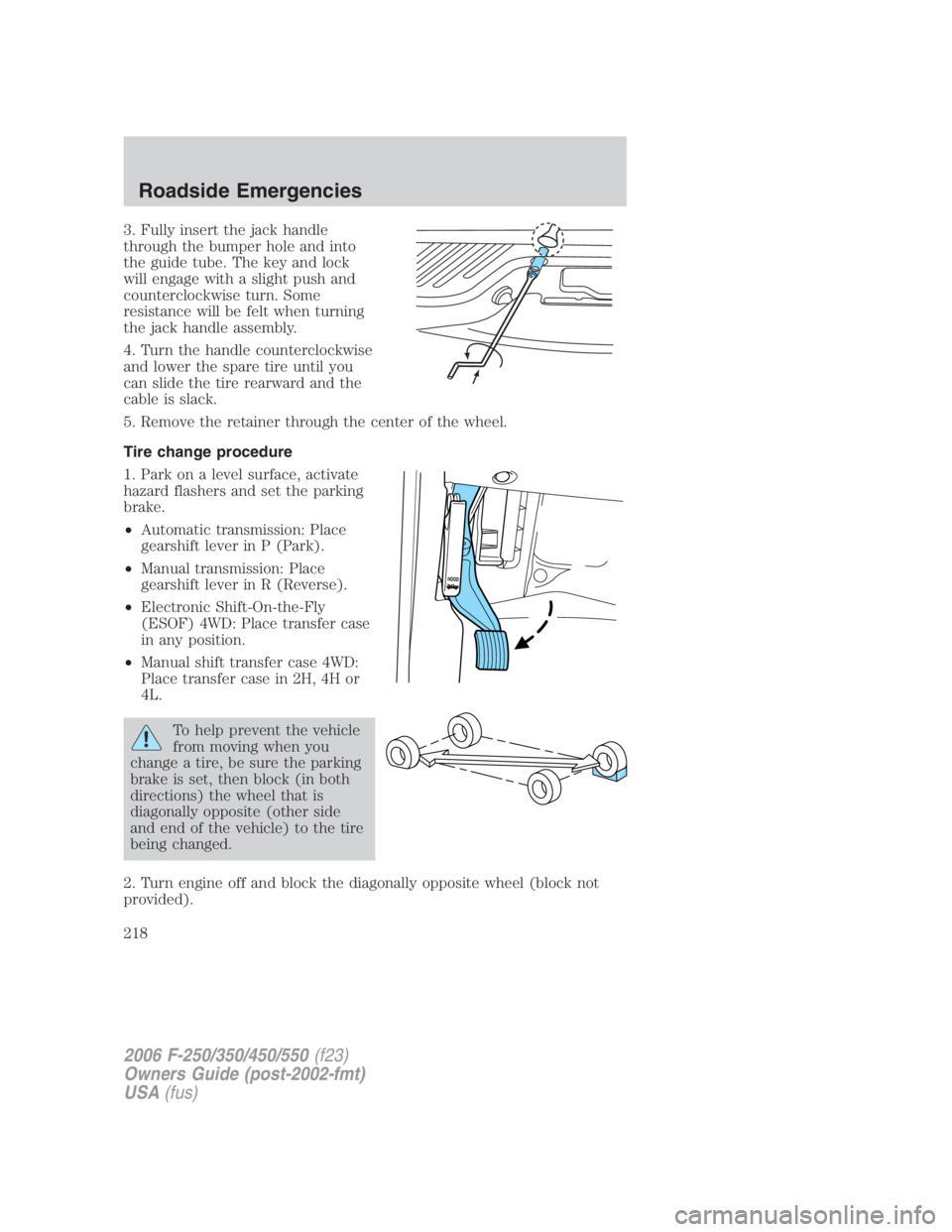
3. Fully insert the jack handle
through the bumper hole and into
the guide tube. The key and lock
will engage with a slight push and
counterclockwise turn. Some
resistance will be felt when turning
the jack handle assembly.
4. Turn the handle counterclockwise
and lower the spare tire until you
can slide the tire rearward and the
cable is slack.
5. Remove the retainer through the center of the wheel.
Tire change procedure
1. Park on a level surface, activate
hazard flashers and set the parking
brake.
• Automatic transmission: Place
gearshift lever in P (Park).
• Manual transmission: Place
gearshift lever in R (Reverse).
• Electronic Shift-On-the-Fly
(ESOF) 4WD: Place transfer case
in any position.
• Manual shift transfer case 4WD:
Place transfer case in 2H, 4H or
4L.
To help prevent the vehicle
from moving when you
change a tire, be sure the parking
brake is set, then block (in both
directions) the wheel that is
diagonally opposite (other side
and end of the vehicle) to the tire
being changed.
2. Turn engine off and block the diagonally opposite wheel (block not
provided).
2006 F-250/350/450/550 (f23)
Owners Guide (post-2002-fmt)
USA (fus)Roadside Emergencies
218
Page 221 of 312

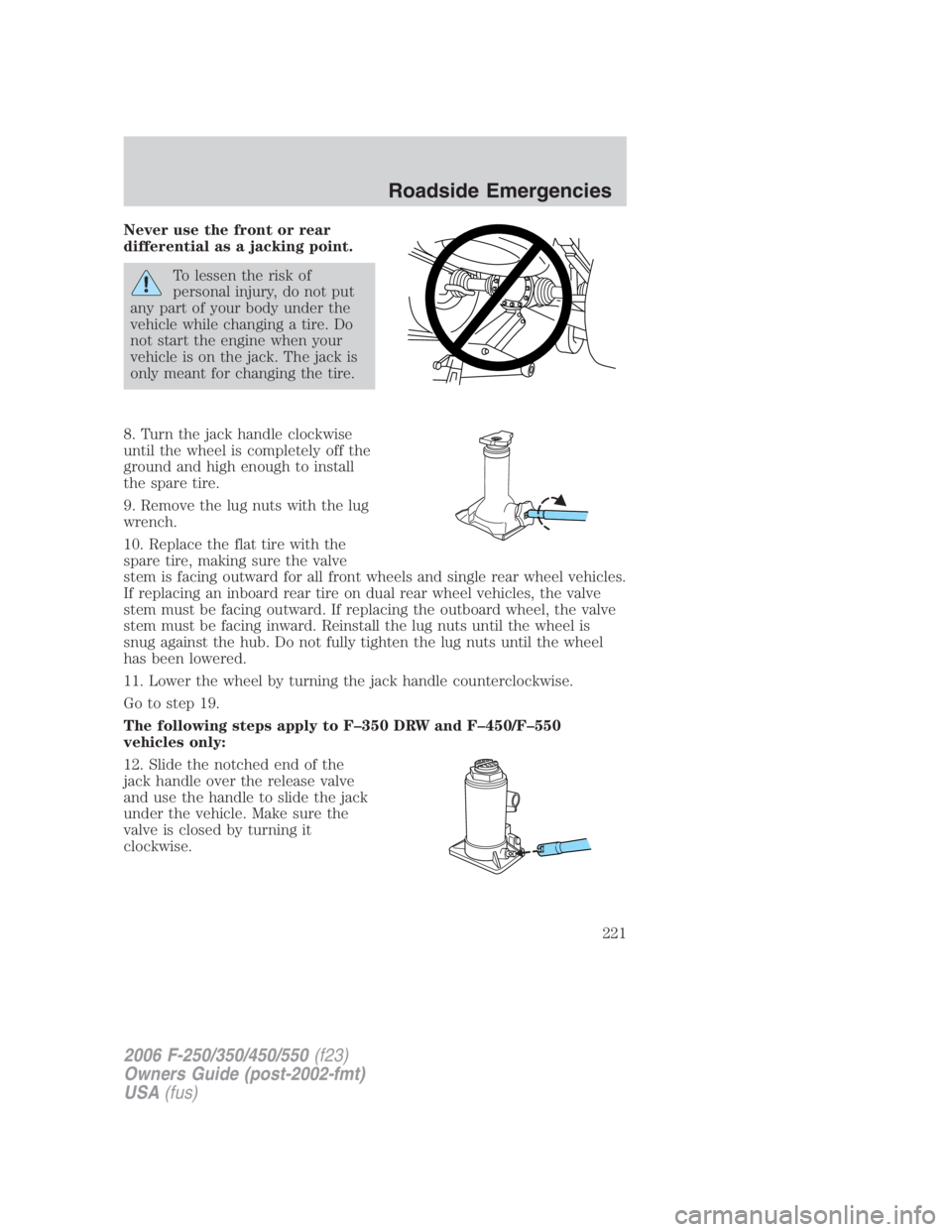
Never use the front or rear
differential as a jacking point.
To lessen the risk of
personal injury, do not put
any part of your body under the
vehicle while changing a tire. Do
not start the engine when your
vehicle is on the jack. The jack is
only meant for changing the tire.
8. Turn the jack handle clockwise
until the wheel is completely off the
ground and high enough to install
the spare tire.
9. Remove the lug nuts with the lug
wrench.
10. Replace the flat tire with the
spare tire, making sure the valve
stem is facing outward for all front wheels and single rear wheel vehicles.
If replacing an inboard rear tire on dual rear wheel vehicles, the valve
stem must be facing outward. If replacing the outboard wheel, the valve
stem must be facing inward. Reinstall the lug nuts until the wheel is
snug against the hub. Do not fully tighten the lug nuts until the wheel
has been lowered.
11. Lower the wheel by turning the jack handle counterclockwise.
Go to step 19.
The following steps apply to F–350 DRW and F–450/F–550
vehicles only:
12. Slide the notched end of the
jack handle over the release valve
and use the handle to slide the jack
under the vehicle. Make sure the
valve is closed by turning it
clockwise.
2006 F-250/350/450/550 (f23)
Owners Guide (post-2002-fmt)
USA (fus) Roadside Emergencies
221
Page 227 of 312

Preparing your vehicle
When the battery is disconnected or a new battery is installed, the
transmission must relearn its shift strategy. As a result, the transmission
may have firm and/or soft shifts. This operation is considered normal and
will not affect function or durability of the transmission. Over time, the
adaptive learning process will fully update transmission operation.
1. Use only a 12–volt supply to start your vehicle.
2. Do not disconnect the battery of the disabled vehicle as this could
damage the vehicle’s electrical system.
3. Park the booster vehicle close to the hood of the disabled vehicle
making sure the two vehicles do not touch. Set the parking brake on
both vehicles and stay clear of the engine cooling fan and other moving
parts.
4. Check all battery terminals and remove any excessive corrosion before
you attach the battery cables. Ensure that vent caps are tight and level.
5. Turn the heater fan on in both vehicles to protect any electrical
surges. Turn all other accessories off.
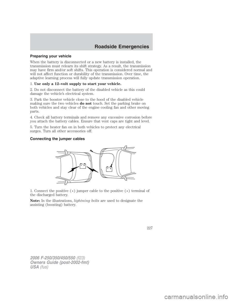
Connecting the jumper cables
1. Connect the positive (+) jumper cable to the positive (+) terminal of
the discharged battery.
Note: In the illustrations, lightning bolts are used to designate the
assisting (boosting) battery.
+
–
+
– 2006 F-250/350/450/550 (f23)
Owners Guide (post-2002-fmt)
USA (fus) Roadside Emergencies
227