Page 50 of 128
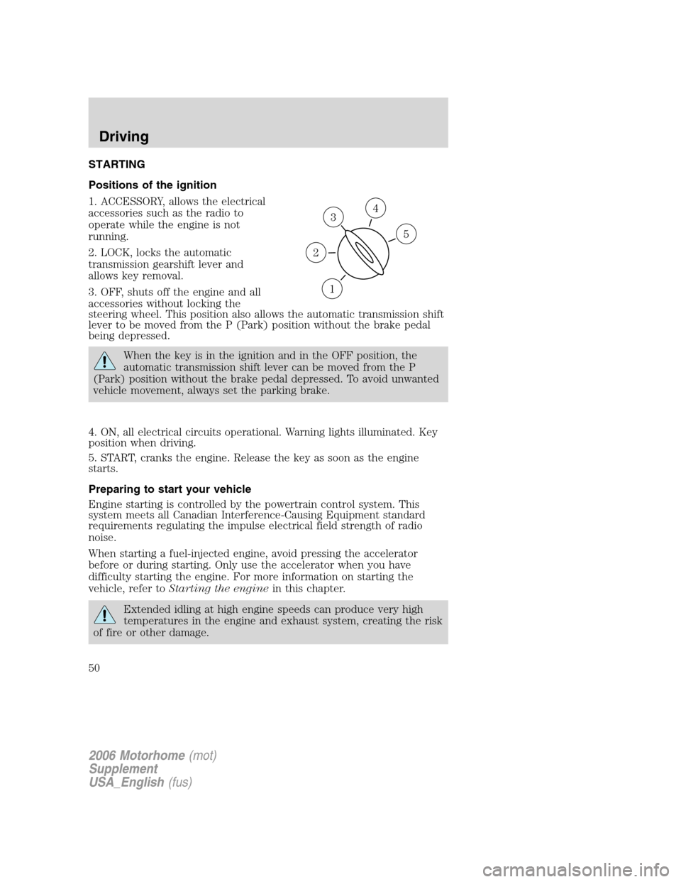
STARTING
Positions of the ignition
1. ACCESSORY, allows the electrical
accessories such as the radio to
operate while the engine is not
running.
2. LOCK, locks the automatic
transmission gearshift lever and
allows key removal.
3. OFF, shuts off the engine and all
accessories without locking the
steering wheel. This position also allows the automatic transmission shift
lever to be moved from the P (Park) position without the brake pedal
being depressed.
When the key is in the ignition and in the OFF position, the
automatic transmission shift lever can be moved from the P
(Park) position without the brake pedal depressed. To avoid unwanted
vehicle movement, always set the parking brake.
4. ON, all electrical circuits operational. Warning lights illuminated. Key
position when driving.
5. START, cranks the engine. Release the key as soon as the engine
starts.
Preparing to start your vehicle
Engine starting is controlled by the powertrain control system. This
system meets all Canadian Interference-Causing Equipment standard
requirements regulating the impulse electrical field strength of radio
noise.
When starting a fuel-injected engine, avoid pressing the accelerator
before or during starting. Only use the accelerator when you have
difficulty starting the engine. For more information on starting the
vehicle, refer toStarting the enginein this chapter.
Extended idling at high engine speeds can produce very high
temperatures in the engine and exhaust system, creating the risk
of fire or other damage.
3
1
2
5
4
2006 Motorhome(mot)
Supplement
USA_English(fus)
Driving
Driving
50
Page 59 of 128
Do not drive your vehicle until you verify that the brakelamps
are working.
Always set the parking brake fully and make sure the gearshift is
latched in P (Park). Turn the ignition to the LOCK position and
remove the key whenever you leave your vehicle.
If the parking brake is fully released, but the brake warning lamp
remains illuminated, the brakes may not be working properly.
See your dealer or a qualified service technician.
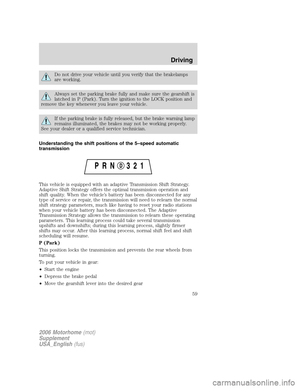
Understanding the shift positions of the 5–speed automatic
transmission
This vehicle is equipped with an adaptive Transmission Shift Strategy.
Adaptive Shift Strategy offers the optimal transmission operation and
shift quality. When the vehicle’s battery has been disconnected for any
type of service or repair, the transmission will need to relearn the normal
shift strategy parameters, much like having to reset your radio stations
when your vehicle battery has been disconnected. The Adaptive
Transmission Strategy allows the transmission to relearn these operating
parameters. This learning process could take several transmission
upshifts and downshifts; during this learning process, slightly firmer
shifts may occur. After this learning process, normal shift feel and shift
scheduling will resume.
P (Park)
This position locks the transmission and prevents the rear wheels from
turning.
To put your vehicle in gear:
•Start the engine
•Depress the brake pedal
•Move the gearshift lever into the desired gear
2006 Motorhome(mot)
Supplement
USA_English(fus)
Driving
59
Page 67 of 128
Fuse/Relay
LocationFuse Amp
RatingPassenger Compartment Fuse
Panel Description
9 20A Stoplamps: Trailer tow Electric
Brake controller feed, Body
builder rear turn/stop feeds, Body
builder stop lamp feed, Trailer
turn/stop fuse feeds
10 10A Instrument cluster memory,
Power brake assist lamp*
11 30A Wiper/Washer module, Wiper feed
12 — Not used
13 10A ABS module
14 10A Warning chime module, Power
brake assist module*, Instrument
cluster power, Instrument cluster
warning lamps, Transmission
control switch
15 15A Left turn signal feed
16 20A Body builder battery (+12V) feed
17 5A Body builder radio feed
18 — Not used
19 5A DRL relays
20 — Not used
21 15A Right turn signal feed
22 20A Trailer tow turn signals
23 10A Cluster run/start
24 — Not used
25 10A Right-hand low beam headlamp
feed
26 10A Speed control module, Brake shift
interlock actuator
27 2A Brake pressure switch/Speed
control
28 — Not used
2006 Motorhome(mot)
Supplement
USA_English(fus)
Roadside Emergencies
67
Page 70 of 128
Fuse/Relay
LocationFuse Amp
RatingPower Distribution Box
Description
1 5A* Power brake assist module***
2 10A* A/C system
3 20A* Transmission, Vapor Management
Valve (VMV) solenoid, Heated
exhaust gas oxygen (HEGO)
sensors
4 5A* Powertrain Control Module (PCM)
memory
5 20A* PCM power, Fuel pump relay coil,
Fuel injectors, Mass Air Flow
(MAF) sensor with IAT, A/C
system relay coil
6 20A* Parklamp feeds, Instrument panel
fuse #41, Warning chime module,
Trailer tow running lamp relay
coil, I/P dimmer module
7 10A* Starter relay coil, BB neutral
sense
8 10A* Stoplamp switch (logic): Power
brake assist module***, Speed
control module, PCM, Anti-lock
Brake System (ABS) module,
Brake shift interlock actuator
9 — Not used
10 20A* Daytime Running Lamps (DRL)
11 30A* Ignition coils, Radio capacitors #1
and #2, PCM relay
12 25A* Trailer tow running lamps feed,
Trailer tow back-up lamps feed, IP
- backup lamp feed
13 30A** Trailer tow electric brake
controller feed
14 60A** IP battery feed (fuse #9, 15, 21)
2006 Motorhome(mot)
Supplement
USA_English(fus)
Roadside Emergencies
70
Page 94 of 128
5. Turn the A/C on and allow the engine to idle for at least one minute.
6. With your foot on the brake pedal and with the A/C on, put the
vehicle in D (Drive) and allow the engine to idle for at least one minute.
7. Drive the vehicle to complete the relearning process.
•The vehicle may need to be driven 10 miles (16 km) or more to
relearn the idle and fuel trim strategy.
•If you do not allow the engine to relearn its idle trim, the idle
quality of your vehicle may be adversely affected until the idle
trim is eventually relearned.
If the battery has been disconnected or a new battery has been installed,
the clock and the preset radio stations must be reset once the battery is
reconnected.
•Always dispose of automotive
batteries in a responsible manner.
Follow your local authorized
standards for disposal. Call your
local authorized recycling center
to find out more about recycling
automotive batteries.
ENGINE COOLANT
Checking engine coolant
The concentration and level of engine coolant should be checked at the
mileage intervals listed inscheduled maintenance information.The
coolant concentration should be maintained at 50/50 coolant and distilled
water, which equates to a freeze point of -34°F (-36°C). Coolant
concentration testing is possible with a hydrometer or antifreeze tester
(such as the Rotunda Battery and Antifreeze Tester, 014–R1060). The
level of coolant should be maintained at the “FULL COLD” level or
within the “COLD FILL RANGE” in the coolant reservoir. If the level falls
below, add coolant per the instructions in theAdding engine coolant
section.
Your vehicle was factory-filled with a 50/50 engine coolant and water
concentration. If the concentration of coolant falls below 40% or above
60%, the engine parts could become damaged or not work properly.A
50–50 mixture of coolant and water provides the following:
L
E
A
D
RETURN
RECYCLE
2006 Motorhome(mot)
Supplement
USA_English(fus)
Maintenance and Specifications
94