Page 64 of 128

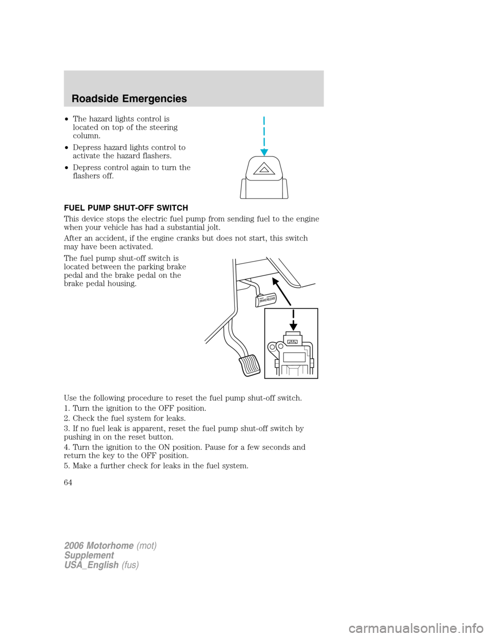
•The hazard lights control is
located on top of the steering
column.
•Depress hazard lights control to
activate the hazard flashers.
•Depress control again to turn the
flashers off.
FUEL PUMP SHUT-OFF SWITCH
This device stops the electric fuel pump from sending fuel to the engine
when your vehicle has had a substantial jolt.
After an accident, if the engine cranks but does not start, this switch
may have been activated.
The fuel pump shut-off switch is
located between the parking brake
pedal and the brake pedal on the
brake pedal housing.
Use the following procedure to reset the fuel pump shut-off switch.
1. Turn the ignition to the OFF position.
2. Check the fuel system for leaks.
3. If no fuel leak is apparent, reset the fuel pump shut-off switch by
pushing in on the reset button.
4. Turn the ignition to the ON position. Pause for a few seconds and
return the key to the OFF position.
5. Make a further check for leaks in the fuel system.
2006 Motorhome(mot)
Supplement
USA_English(fus)
Roadside Emergencies
64
Page 65 of 128
FUSES AND RELAYS
Standard fuse amperage rating and color
COLOR
Fuse
ratingMini
fusesStandard
fusesMaxi
fusesCartridge
maxi
fusesFuse link
cartridge
2A Grey Grey — — —
3A Violet Violet — — —
4A Pink Pink — — —
5A Tan Tan — — —
7.5A Brown Brown — — —
10A Red Red — — —
15A Blue Blue — — —
20A Yellow Yellow Yellow Blue Blue
25A Natural Natural — — —
30A Green Green Green Pink Pink
40A — — Orange Green Green
50A — — Red Red Red
60A — — Blue — Yellow
70A — — Tan — Brown
80A — — Natural — Black
Passenger compartment fuse panel
The fuse panel is located below and to the left of the steering wheel by
the brake pedal. Remove the panel cover to access the fuses.
To remove a fuse use the fuse puller tool provided on the fuse panel
cover.
2006 Motorhome(mot)
Supplement
USA_English(fus)
Roadside Emergencies
65
Page 67 of 128
Fuse/Relay
LocationFuse Amp
RatingPassenger Compartment Fuse
Panel Description
9 20A Stoplamps: Trailer tow Electric
Brake controller feed, Body
builder rear turn/stop feeds, Body
builder stop lamp feed, Trailer
turn/stop fuse feeds
10 10A Instrument cluster memory,
Power brake assist lamp*
11 30A Wiper/Washer module, Wiper feed
12 — Not used
13 10A ABS module
14 10A Warning chime module, Power
brake assist module*, Instrument
cluster power, Instrument cluster
warning lamps, Transmission
control switch
15 15A Left turn signal feed
16 20A Body builder battery (+12V) feed
17 5A Body builder radio feed
18 — Not used
19 5A DRL relays
20 — Not used
21 15A Right turn signal feed
22 20A Trailer tow turn signals
23 10A Cluster run/start
24 — Not used
25 10A Right-hand low beam headlamp
feed
26 10A Speed control module, Brake shift
interlock actuator
27 2A Brake pressure switch/Speed
control
28 — Not used
2006 Motorhome(mot)
Supplement
USA_English(fus)
Roadside Emergencies
67
Page 68 of 128
Fuse/Relay
LocationFuse Amp
RatingPassenger Compartment Fuse
Panel Description
29 — Not used
30 — Not used
31 10A Left-hand low beam headlamp
feed
32 10A Backup lamp feed
33 10A Reverse lamps
34 10A Trailer tow reverse lamps
35 20A Body builder high beam feed,
High beam indicator, DRL
36 — Not used
37 — Not used
38 10A Body builder accessory feed (run
only)
39 — Not used
40 — Not used
41 10A Instrument illumination
42 — Not used
43 — Not used
44 — Not used
Relay 1 — Left turn signal
Relay 2 — Right turn signal
Relay 3 — Trailer tow left turn signal
Relay 4 — Trailer tow right turn signal
Relay 5 — Not used
Relay 6 — DRL, Parking brake
Relay 7 — DRL on/off
Relay 8 — Not used
Relay 9 — Not used
Relay 10 — Not used
*Vehicles with Hydromax brake assist only
2006 Motorhome(mot)
Supplement
USA_English(fus)
Roadside Emergencies
68
Page 70 of 128

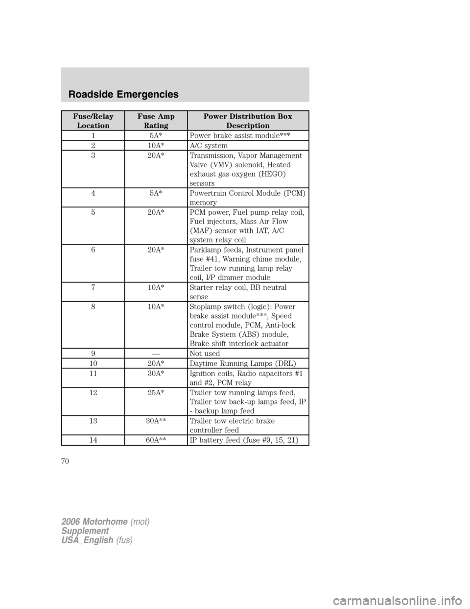
Fuse/Relay
LocationFuse Amp
RatingPower Distribution Box
Description
1 5A* Power brake assist module***
2 10A* A/C system
3 20A* Transmission, Vapor Management
Valve (VMV) solenoid, Heated
exhaust gas oxygen (HEGO)
sensors
4 5A* Powertrain Control Module (PCM)
memory
5 20A* PCM power, Fuel pump relay coil,
Fuel injectors, Mass Air Flow
(MAF) sensor with IAT, A/C
system relay coil
6 20A* Parklamp feeds, Instrument panel
fuse #41, Warning chime module,
Trailer tow running lamp relay
coil, I/P dimmer module
7 10A* Starter relay coil, BB neutral
sense
8 10A* Stoplamp switch (logic): Power
brake assist module***, Speed
control module, PCM, Anti-lock
Brake System (ABS) module,
Brake shift interlock actuator
9 — Not used
10 20A* Daytime Running Lamps (DRL)
11 30A* Ignition coils, Radio capacitors #1
and #2, PCM relay
12 25A* Trailer tow running lamps feed,
Trailer tow back-up lamps feed, IP
- backup lamp feed
13 30A** Trailer tow electric brake
controller feed
14 60A** IP battery feed (fuse #9, 15, 21)
2006 Motorhome(mot)
Supplement
USA_English(fus)
Roadside Emergencies
70
Page 71 of 128
Fuse/Relay
LocationFuse Amp
RatingPower Distribution Box
Description
15 20A Trailer tow park lamps
16 60A** ABS module
17 — Not used
18 20A** Horn feed
19 — Not used
20 40A** PCM relay
21 20A** Fuel pump motor
22 20A** Diagnostic tool connector, Cigar
lighter feed
23 40A** Blower motor feed
24 50A** IP battery feed (fuses #4, 10, 16)
25 40A** Ignition switch feed (IP fuses #1,
5, 7, 11, 13, 14, 17, 19, PDB fuses
#7, 9, 11)
26 40A** Ignition switch feed (IP fuses #5,
11, 17, 26, 32, 38)
27 30A** Multifunction switch (headlamps)
28 30A** Starter solenoid
29 60A** Power brake assist motor***
Relay 1 — A/C clutch
Relay 2 — Fuel pump relay
Relay 3 — Horn relay
Relay 4 — Not used
Relay 5 — Blower motor relay
Relay 6 — PCM relay
Diode 1 — PCM diode
Diode 2 — Park brake diode
* Mini Fuses ** Maxi Fuses ***Vehicles with Hydromax brake assist
only
2006 Motorhome(mot)
Supplement
USA_English(fus)
Roadside Emergencies
71
Page 73 of 128

Preparing your vehicle
When the battery is disconnected or a new battery is installed, the
transmission must relearn its shift strategy. As a result, the transmission
may have firm and/or soft shifts. This operation is considered normal and
will not affect function or durability of the transmission. Over time, the
adaptive learning process will fully update transmission operation.
1.Use only a 12–volt supply to start your vehicle.
2. Do not disconnect the battery of the disabled vehicle as this could
damage the vehicle’s electrical system.
3. Park the booster vehicle close to the hood of the disabled vehicle
making sure the two vehiclesdo nottouch. Set the parking brake on
both vehicles and stay clear of the engine cooling fan and other moving
parts.
4. Check all battery terminals and remove any excessive corrosion before
you attach the battery cables. Ensure that vent caps are tight and level.
5. Turn the heater fan on in both vehicles to protect any electrical
surges. Turn all other accessories off.
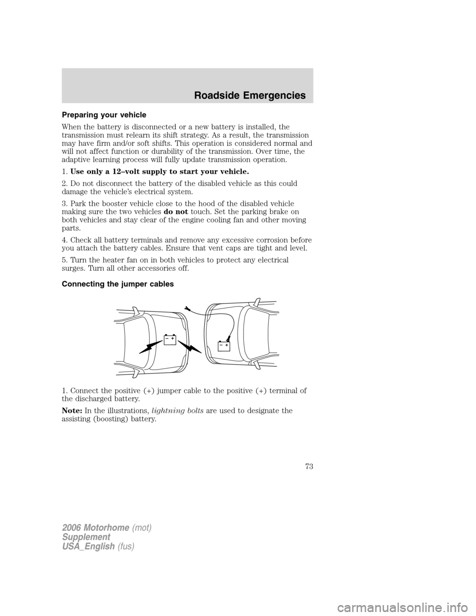
Connecting the jumper cables
1. Connect the positive (+) jumper cable to the positive (+) terminal of
the discharged battery.
Note:In the illustrations,lightning boltsare used to designate the
assisting (boosting) battery.
+–+–
2006 Motorhome(mot)
Supplement
USA_English(fus)
Roadside Emergencies
73
Page 86 of 128

CLEANING THE WHEELS
•Clean weekly with Motorcraft Wheel and Tire Cleaner (ZC-37–A),
which is available from your dealer. Heavy dirt and brake dust
accumulation may require agitation with a sponge. Rinse thoroughly
with a strong stream of water.
•Never apply any cleaning chemical to hot or warm wheel rims or
covers.
•Some automatic car washes may cause damage to the finish on your
wheel rims or covers. Chemical-strength cleaners, or cleaning
chemicals, in combination with brush agitation to remove brake dust
and dirt, could wear away the clearcoat finish over time.
•Do not use hydrofluoric acid-based or high caustic-based wheel
cleaners, steel wool, fuels or strong household detergent.
•To remove tar and grease, use Motorcraft Bug and Tar Remover
(ZC-42), available from your dealer.
ENGINE
Engines are more efficient when they are clean because grease and dirt
buildup keep the engine warmer than normal. When washing:
•Take care when using a power washer to clean the engine. The
high-pressure fluid could penetrate the sealed parts and cause
damage.
•Do not spray a hot engine with cold water to avoid cracking the
engine block or other engine components.
•Spray Motorcraft Engine Shampoo and Degreaser (ZC-20) on all parts
that require cleaning and pressure rinse clean.
•Never wash or rinse the engine while it is running; water in the
running engine may cause internal damage.
UNDERBODY
Flush the complete underside of your vehicle frequently. Keep body and
door drain holes free from packed dirt.
2006 Motorhome(mot)
Supplement
USA_English(fus)
Cleaning
Cleaning
86