Page 69 of 360
•in valleys and in mountainous regions
The GPS signal strength may vary. The directional heading indicator at
the bottom of the screen might change color to indicate this signal
strength. The colors are as follows:
•Green — A clear GPS signal is being received.
•Yellow — The GPS signal is partially blocked.
•Red — The GPS signal is unavailable and may be temporarily blocked.
To enter navigation mode
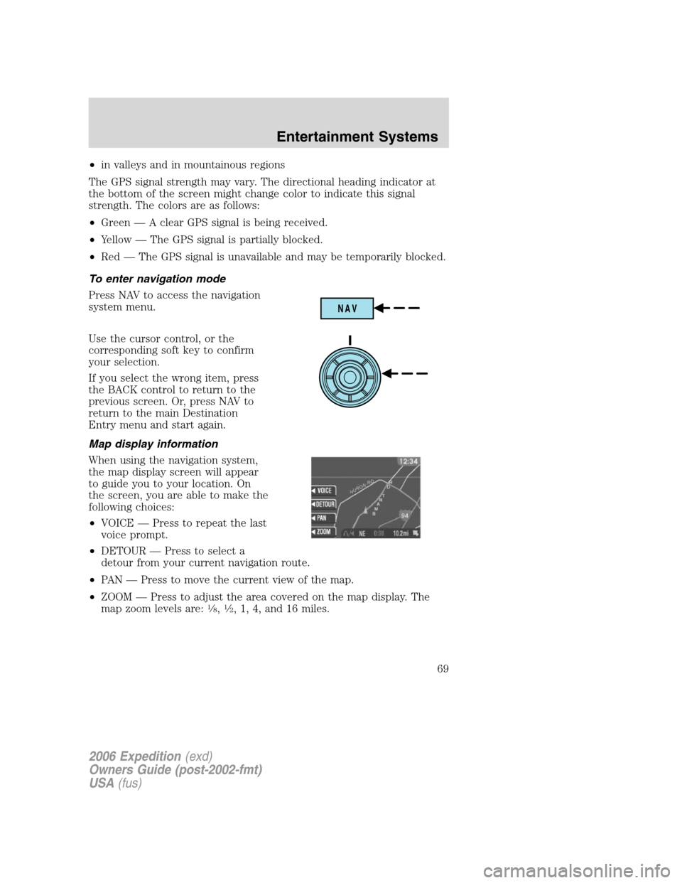
Press NAV to access the navigation
system menu.
Use the cursor control, or the
corresponding soft key to confirm
your selection.
If you select the wrong item, press
the BACK control to return to the
previous screen. Or, press NAV to
return to the main Destination
Entry menu and start again.
Map display information
When using the navigation system,
the map display screen will appear
to guide you to your location. On
the screen, you are able to make the
following choices:
•VOICE — Press to repeat the last
voice prompt.
•DETOUR — Press to select a
detour from your current navigation route.
•PAN — Press to move the current view of the map.
•ZOOM — Press to adjust the area covered on the map display. The
map zoom levels are:
1�8,1�2, 1, 4, and 16 miles.
NAV
2006 Expedition(exd)
Owners Guide (post-2002-fmt)
USA(fus)
Entertainment Systems
69
Page 96 of 360
5. Locate the vertical adjuster on
each headlamp, then use a 10 mm
socket/wrench to turn the adjuster
either counterclockwise (to adjust
down) or clockwise (to adjust up)
aligning the upper edge of the light
pattern up to the horizontal line.
6. HORIZONTAL AIM IS NOT
REQUIRED FOR THIS VEHICLE
AND IS NON-ADJUSTABLE.
7. Repeat Steps 3–5 for the other headlamp.
8. Close the hood and turn off the lamps.
TURN SIGNAL CONTROL
•Push down to activate the left
turn signal.
•Push up to activate the right turn
signal.
INTERIOR LAMPS
Front row map lamps (if equipped)
To turn on the map lamps, press the
rear edge of the lamp.
INT2OFFOFFINT1
2006 Expedition(exd)
Owners Guide (post-2002-fmt)
USA(fus)
Lights
96
Page 98 of 360

BULB REPLACEMENT
Headlamp Condensation
The headlamps are vented to equalize pressure. When moist air enters
the headlamp(s) through the vents, there is a possibility that
condensation can occur. This condensation is normal and will clear
within 45 minutes of headlamp operation.
Replacing exterior bulbs
Check the operation of all the bulbs frequently.
Using the right bulbs
Replacement bulbs are specified in the chart below. Headlamp bulbs
must be marked with an authorized “D.O.T.” for North America to ensure
lamp performance, light brightness and pattern and safe visibility. The
correct bulbs will not damage the lamp assembly or void the lamp
assembly warranty and will provide quality bulb burn time.
Function Number of bulbs Trade number
Headlamps (low-beam) 2 9006
Headlamps (high-beam) 2 9005
Front park/turn/sidemarker
lamps2 3457 K
Foglamps 2 899
Front row map lamps 2 579
Front row map/dome lamps 3 578
Rear cargo lamp 1 578
2nd row reading lamp 2 578
Turn/tail/brake/sidemarker
lamps2 3157K or 4157K
Approach/mirror turn signal
lamps (if equipped)2 906
Mirror approach lamps –
non turn signal (if
equipped)2 *See your dealer
Liftgate bulb 2 916
Backup lamp 2 3156
2006 Expedition(exd)
Owners Guide (post-2002-fmt)
USA(fus)
Lights
98
Page 101 of 360
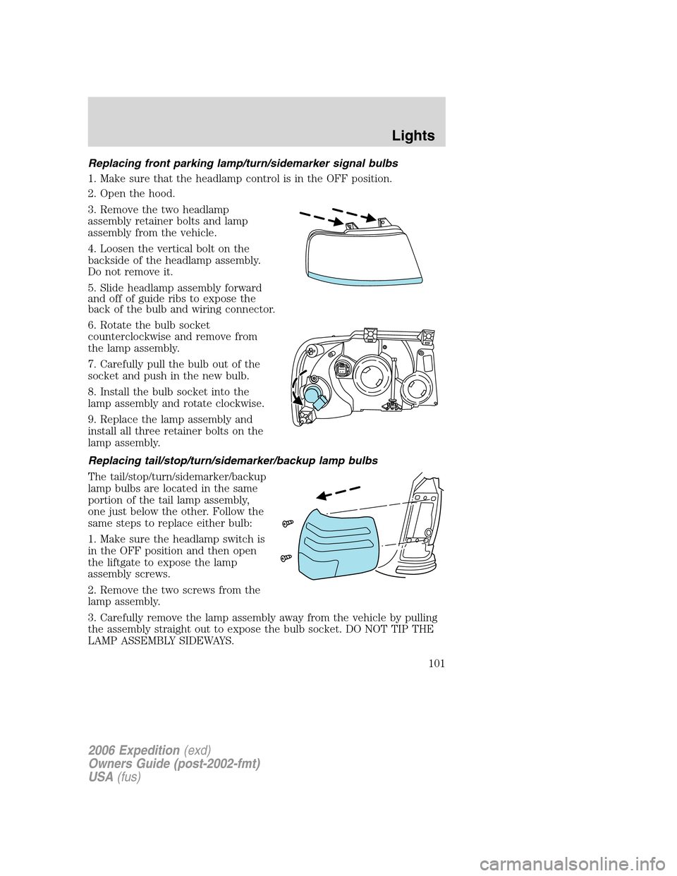
Replacing front parking lamp/turn/sidemarker signal bulbs
1. Make sure that the headlamp control is in the OFF position.
2. Open the hood.
3. Remove the two headlamp
assembly retainer bolts and lamp
assembly from the vehicle.
4. Loosen the vertical bolt on the
backside of the headlamp assembly.
Do not remove it.
5. Slide headlamp assembly forward
and off of guide ribs to expose the
back of the bulb and wiring connector.
6. Rotate the bulb socket
counterclockwise and remove from
the lamp assembly.
7. Carefully pull the bulb out of the
socket and push in the new bulb.
8. Install the bulb socket into the
lamp assembly and rotate clockwise.
9. Replace the lamp assembly and
install all three retainer bolts on the
lamp assembly.
Replacing tail/stop/turn/sidemarker/backup lamp bulbs
The tail/stop/turn/sidemarker/backup
lamp bulbs are located in the same
portion of the tail lamp assembly,
one just below the other. Follow the
same steps to replace either bulb:
1. Make sure the headlamp switch is
in the OFF position and then open
the liftgate to expose the lamp
assembly screws.
2. Remove the two screws from the
lamp assembly.
3. Carefully remove the lamp assembly away from the vehicle by pulling
the assembly straight out to expose the bulb socket. DO NOT TIP THE
LAMP ASSEMBLY SIDEWAYS.
2006 Expedition(exd)
Owners Guide (post-2002-fmt)
USA(fus)
Lights
101
Page 104 of 360
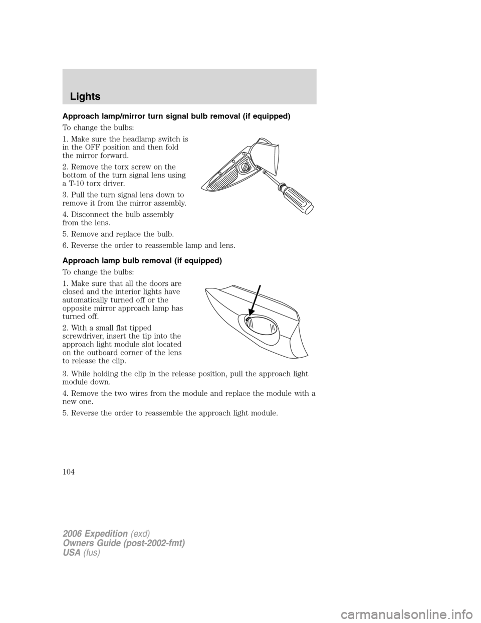
Approach lamp/mirror turn signal bulb removal (if equipped)
To change the bulbs:
1. Make sure the headlamp switch is
in the OFF position and then fold
the mirror forward.
2. Remove the torx screw on the
bottom of the turn signal lens using
a T-10 torx driver.
3. Pull the turn signal lens down to
remove it from the mirror assembly.
4. Disconnect the bulb assembly
from the lens.
5. Remove and replace the bulb.
6. Reverse the order to reassemble lamp and lens.
Approach lamp bulb removal (if equipped)
To change the bulbs:
1. Make sure that all the doors are
closed and the interior lights have
automatically turned off or the
opposite mirror approach lamp has
turned off.
2. With a small flat tipped
screwdriver, insert the tip into the
approach light module slot located
on the outboard corner of the lens
to release the clip.
3. While holding the clip in the release position, pull the approach light
module down.
4. Remove the two wires from the module and replace the module with a
new one.
5. Reverse the order to reassemble the approach light module.
2006 Expedition(exd)
Owners Guide (post-2002-fmt)
USA(fus)
Lights
104
Page 114 of 360
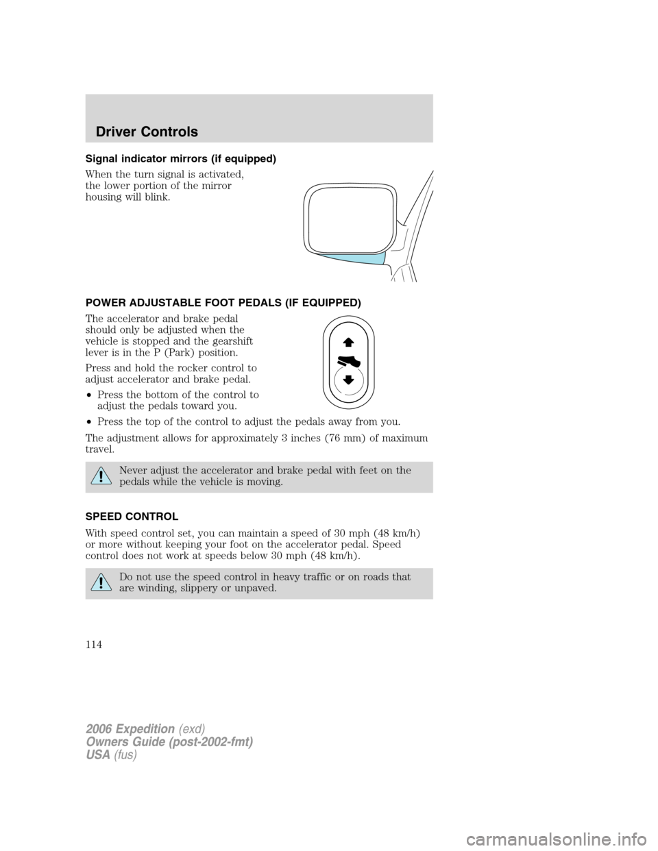
Signal indicator mirrors (if equipped)
When the turn signal is activated,
the lower portion of the mirror
housing will blink.
POWER ADJUSTABLE FOOT PEDALS (IF EQUIPPED)
The accelerator and brake pedal
should only be adjusted when the
vehicle is stopped and the gearshift
lever is in the P (Park) position.
Press and hold the rocker control to
adjust accelerator and brake pedal.
•Press the bottom of the control to
adjust the pedals toward you.
•Press the top of the control to adjust the pedals away from you.
The adjustment allows for approximately 3 inches (76 mm) of maximum
travel.
Never adjust the accelerator and brake pedal with feet on the
pedals while the vehicle is moving.
SPEED CONTROL
With speed control set, you can maintain a speed of 30 mph (48 km/h)
or more without keeping your foot on the accelerator pedal. Speed
control does not work at speeds below 30 mph (48 km/h).
Do not use the speed control in heavy traffic or on roads that
are winding, slippery or unpaved.
2006 Expedition(exd)
Owners Guide (post-2002-fmt)
USA(fus)
Driver Controls
114
Page 120 of 360
Retain the original transmitter for use in other vehicles as well as for
future programming procedures (i.e. new HomeLink�equipped vehicle
purchase). It is also suggested that upon the sale of the vehicle, the
programmed Homelink�buttons be erased for security purposes, refer to
Programmingin this section.
Programming
Do not program HomeLink�with the vehicle parked in the garage.
Note:Your vehicle may require the ignition switch to be turned to the
ACC position for programming and/or operation of the HomeLink�.Itis
also recommended that a new battery be placed in the hand-held
transmitter of the device being programmed to HomeLink�for quicker
training and accurate transmission of the radio-frequency signal.
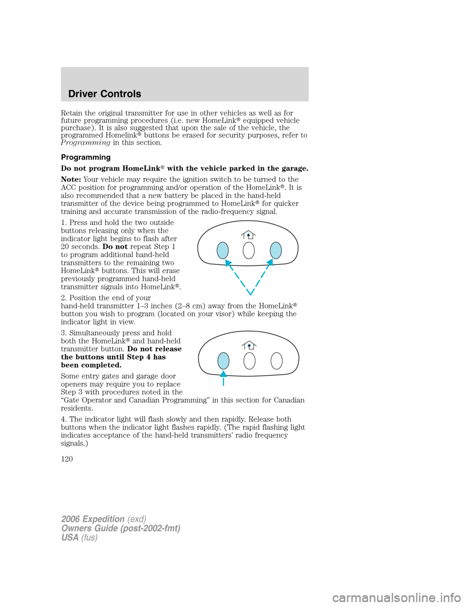
1. Press and hold the two outside
buttons releasing only when the
indicator light begins to flash after
20 seconds.Do notrepeat Step 1
to program additional hand-held
transmitters to the remaining two
HomeLink�buttons. This will erase
previously programmed hand-held
transmitter signals into HomeLink�.
2. Position the end of your
hand-held transmitter 1–3 inches (2–8 cm) away from the HomeLink�
button you wish to program (located on your visor) while keeping the
indicator light in view.
3. Simultaneously press and hold
both the HomeLink�and hand-held
transmitter button.Do not release
the buttons until Step 4 has
been completed.
Some entry gates and garage door
openers may require you to replace
Step 3 with procedures noted in the
“Gate Operator and Canadian Programming” in this section for Canadian
residents.
4. The indicator light will flash slowly and then rapidly. Release both
buttons when the indicator light flashes rapidly. (The rapid flashing light
indicates acceptance of the hand-held transmitters’ radio frequency
signals.)
2006 Expedition(exd)
Owners Guide (post-2002-fmt)
USA(fus)
Driver Controls
120
Page 121 of 360
5. Press and hold the just-trained HomeLink�button and observe the
indicator light. If the light is constant, programming is complete and your
device should activate when the HomeLink�button is pressed and
released.Note:To program the remaining two HomeLink�buttons,
begin with Step 2 in the “Programming” section —do notrepeat Step 1.
Note:If the indicator light blinks rapidly for two seconds and then turns
to a continuous red, proceed with Steps 6 through 8 to complete
programming of a rolling code equipped device.
6. At the garage door opener receiver (motor-head unit) in the garage,
locate the “learn” or “smart” button (usually near where the hanging
antenna wire is attached to the unit).
7. Press and release the “learn” or “smart” button. (The name and color
of the button may vary by manufacturer.)
Note:There are 30 seconds in which to initiate Step 8.
8. Return to the vehicle and firmly press, hold for two seconds and
release the HomeLink�button. Repeat the press/hold/release sequence
again, and, depending on the brand of the garage door opener (or other
rolling code equipped device), repeat this sequence a third time to
complete the programming.
HomeLink�should now activate your rolling code equipped device. To
program additional HomeLink�buttons begin with Step 2 in the
“Programming” section. For questions or comments, please contact
HomeLink atwww.homelink.comor1–800–355–3515.
Gate Operator & Canadian Programming
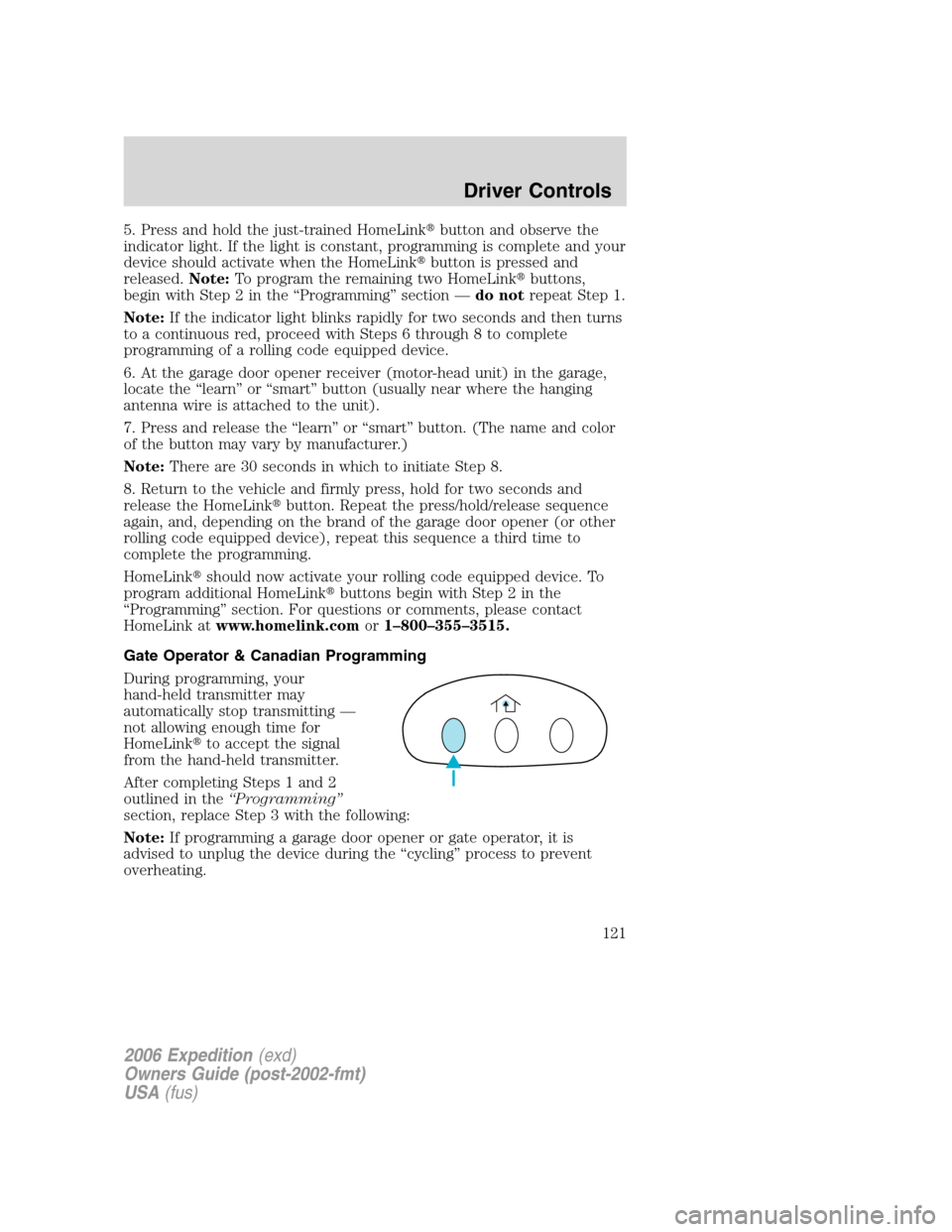
During programming, your
hand-held transmitter may
automatically stop transmitting —
not allowing enough time for
HomeLink�to accept the signal
from the hand-held transmitter.
After completing Steps 1 and 2
outlined in the“Programming”
section, replace Step 3 with the following:
Note:If programming a garage door opener or gate operator, it is
advised to unplug the device during the “cycling” process to prevent
overheating.
2006 Expedition(exd)
Owners Guide (post-2002-fmt)
USA(fus)
Driver Controls
121