Page 153 of 256

•Selecting 2 (Second) at higher speeds will cause the transmission to
downshift to second gear at the appropriate vehicle speed.
1 (First)
•Provides maximum engine braking.
•Allows upshifts by moving gearshift lever.
•Will not downshift into 1 (First) at high speeds; allows for 1 (First)
when vehicle reaches slower speeds.
Forced downshifts
•Allowed in
(Overdrive) or Drive.
•Depress the accelerator to the floor.
•Allows transmission to select an appropriate gear.
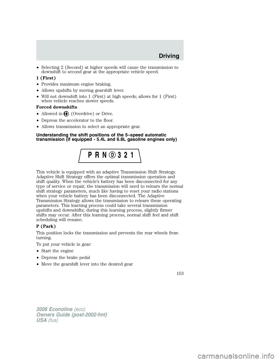
Understanding the shift positions of the 5–speed automatic
transmission (if equipped - 5.4L and 6.8L gasoline engines only)
This vehicle is equipped with an adaptive Transmission Shift Strategy.
Adaptive Shift Strategy offers the optimal transmission operation and
shift quality. When the vehicle’s battery has been disconnected for any
type of service or repair, the transmission will need to relearn the normal
shift strategy parameters, much like having to reset your radio stations
when your vehicle battery has been disconnected. The Adaptive
Transmission Strategy allows the transmission to relearn these operating
parameters. This learning process could take several transmission
upshifts and downshifts; during this learning process, slightly firmer
shifts may occur. After this learning process, normal shift feel and shift
scheduling will resume.
P (Park)
This position locks the transmission and prevents the rear wheels from
turning.
To put your vehicle in gear:
•Start the engine
•Depress the brake pedal
•Move the gearshift lever into the desired gear
2006 Econoline(eco)
Owners Guide (post-2002-fmt)
USA(fus)
Driving
153
Page 160 of 256

ROADSIDE ASSISTANCE
Getting roadside assistance
To fully assist you should you have a vehicle concern, Ford Motor
Company offers a complimentary roadside assistance program. This
program is separate from the New Vehicle Limited Warranty. The service
is available:
•24–hours, seven days a week
•for the New Vehicle Limited Warranty period of three years or 36,000
miles (60,000 km), whichever occurs first on Ford and Mercury
vehicles, and four years or 50,000 miles (80,000 km) on Lincoln
vehicles.
Roadside assistance will cover:
•a flat tire change with a good spare (except Ford GT which has a tire
inflation kit)
•battery jump start
•lock-out assistance (key replacement cost is the customer’s
responsibility)
•fuel delivery – Independent Service Contractors, if not prohibited by
state, local or municipal law shall deliver up to 2.0 gallons (7.5L) of
gasoline or 5 gallons (18.9L) of diesel fuel to a disabled vehicle. Fuel
delivery service is limited to two no-charge occurrences within a
12-month period.
•winch out – available within 100 feet (30.5 meters) of a paved or
county maintained road, no recoveries.
•towing – Ford/Mercury/Lincoln eligible vehicle towed to an authorized
dealer within 35 miles (56.3 km) of the disablement location or to the
nearest authorized dealer. If a member requests to be towed to an
authorized dealer more than 35 miles (56.3 km) from the disablement
location, the member shall be responsible for any mileage costs in
excess of 35 miles (56.3 km).
Trailers shall be covered up to $100 if the disabled eligible vehicle
requires service at the nearest authorized dealer. If the trailer is disabled,
but the towing vehicle is operational, the trailer does not qualify for any
roadside services.
2006 Econoline(eco)
Owners Guide (post-2002-fmt)
USA(fus)
Roadside Emergencies
160
Page 162 of 256
HAZARD FLASHER
The hazard flasher is located on the
steering column, just behind the
steering wheel. The hazard flashers
will operate when the ignition is in
any position or if the key is not in
the ignition.
Push in the flasher control and all
front and rear direction signals will
flash. Press the flasher control again
to turn them off. Use it when your
vehicle is disabled and is creating a
safety hazard for other motorists.
Note:With extended use, the flasher may run down your battery.
FUEL PUMP SHUT-OFF SWITCH
This device stops the electric fuel pump from sending fuel to the engine
when your vehicle has had a substantial jolt.
After an accident, if the engine cranks but does not start, this switch
may have been activated.
2006 Econoline(eco)
Owners Guide (post-2002-fmt)
USA(fus)
Roadside Emergencies
162
Page 166 of 256

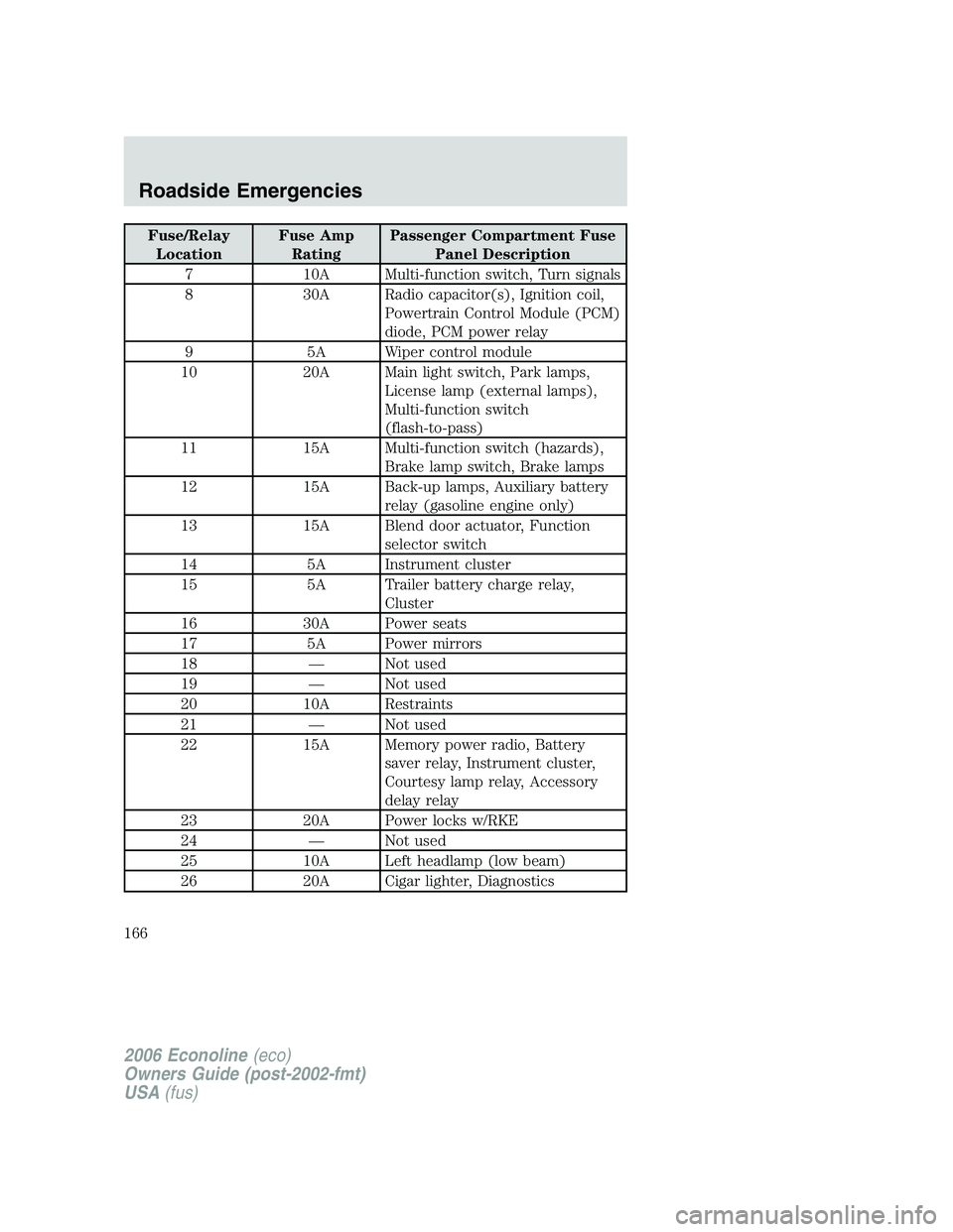
Fuse/Relay
LocationFuse Amp
RatingPassenger Compartment Fuse
Panel Description
7 10A Multi-function switch, Turn signals
8 30A Radio capacitor(s), Ignition coil,
Powertrain Control Module (PCM)
diode, PCM power relay
9 5A Wiper control module
10 20A Main light switch, Park lamps,
License lamp (external lamps),
Multi-function switch
(flash-to-pass)
11 15A Multi-function switch (hazards),
Brake lamp switch, Brake lamps
12 15A Back-up lamps, Auxiliary battery
relay (gasoline engine only)
13 15A Blend door actuator, Function
selector switch
14 5A Instrument cluster
15 5A Trailer battery charge relay,
Cluster
16 30A Power seats
17 5A Power mirrors
18 — Not used
19 — Not used
20 10A Restraints
21 — Not used
22 15A Memory power radio, Battery
saver relay, Instrument cluster,
Courtesy lamp relay, Accessory
delay relay
23 20A Power locks w/RKE
24 — Not used
25 10A Left headlamp (low beam)
26 20A Cigar lighter, Diagnostics
2006 Econoline(eco)
Owners Guide (post-2002-fmt)
USA(fus)
Roadside Emergencies
166
Page 167 of 256

Fuse/Relay
LocationFuse Amp
RatingPassenger Compartment Fuse
Panel Description
27 5A Radio
28 — Not used
29 — Not used
30 15A Headlamps (high beam indicator)
31 10A Right headlamp (low beam)
32 20A Power point #1 (instrument
panel)
33 10A Start relay
34 30A IP Body builder connector #3
35 — Not used
36 5A Instrument illumination
37 5A Airbag deactivation switch
38 — Not used
39 10A Trailer tow electric brake, Center
High-Mounted Stop Lamp
(CHMSL), Brake lamps
40 20A Power point #2 (2nd row seating
position - driver side)
41 30A Modified vehicle
42 20A circuit
breakerPower windows
43 — Not used
44 20A circuit
breakerWiper/washer
Power distribution box
The power distribution box is located in the engine compartment. The
power distribution box contains high-current fuses that protect your
vehicle’s main electrical systems from overloads.
Always disconnect the battery before servicing high current
fuses.
2006 Econoline(eco)
Owners Guide (post-2002-fmt)
USA(fus)
Roadside Emergencies
167
Page 168 of 256
To reduce risk of electrical shock, always replace the cover to
the Power Distribution Box before reconnecting the battery or
refilling fluid reservoirs.
If the battery has been disconnected and reconnected, refer to the
Batterysection of theMaintenance and Specificationschapter.
The high-current fuses are coded as follows.
Fuse/Relay
LocationFuse Amp
RatingPower Distribution Box
Description
1 — Powertrain Control Module (PCM)
diode
2 — Auxiliary battery diode
3 15A* Daytime Running Lamps (DRL)
module, A/C clutch
4 5A* Heated PCV (4.6L and 6.8L
gasoline engines)
5 15A* Horn relay
6 2A* Brake pressure switch
7 60A** Ignition switch, Accessory delay
2006 Econoline(eco)
Owners Guide (post-2002-fmt)
USA(fus)
Roadside Emergencies
168
Page 169 of 256

Fuse/Relay
LocationFuse Amp
RatingPower Distribution Box
Description
8 40A** Trailer battery charge relay
9 50A** Modified vehicle power
10 30A** Electric brake controller
11 60A** 4-Wheel Anti-lock Brake System
(4WABS)
40A** AdvanceTrac�with RSC
12 60A** I/P fuses 29, 34, 35, 40 and 41
13 20A** Fuel pump relay
14 50A** Auxiliary blower relay
15 30A** Main light switch
16 20A** Injectors (gasoline engines)
17 50A** Blower motor relay (blower
motor)
18 60A** Engine compartment fuses 3, 5
and 26, Instrument panel fuses 26
and 32, Start relay
19 50A** IDM relay (diesel engine only)
40A** AdvanceTrac�with RSC (gasoline
engines only )
20 60A** Auxiliary battery relay (gasoline
engine only), PDB fuses 8 and 24
21 30A** PCM power relay, PDB fuse 27
22 60A** I/P fuses 4, 5, 10, 11, 16, 17, 22
and 23, Circuit breaker 44
23 10A* Alternator field (diesel engine
only)
20A* CMS, HEGOS, MAF, EGR, A/C
clutch relay (gasoline engine
only)
24 20A* Trailer tow running lamps and
back-up lamp relays
25 — Not used
2006 Econoline(eco)
Owners Guide (post-2002-fmt)
USA(fus)
Roadside Emergencies
169
Page 170 of 256
Fuse/Relay
LocationFuse Amp
RatingPower Distribution Box
Description
26 20A* Trailer tow turn signals
27 10A* PCM
28 — Not used
A — Fuel pump relay
B — Horn relay
C — Trailer back-up lamps relay
D — Trailer running lamps relay
E — Trailer battery charge relay
F — IDM relay (diesel only), IVD
(gasoline only)
G — PCM relay
H — Blower motor relay
J — Accessory delay relay
K — Start relay
* Mini fuses ** Maxi fuses
Relay modules
Instrument panel relay module
The instrument panel relay module is located behind the radio in the
center of the instrument panel. Have your authorized dealer service this
module, if required.
The relays are coded as follows:
2006 Econoline(eco)
Owners Guide (post-2002-fmt)
USA(fus)
Roadside Emergencies
170