2006 FORD CROWN VICTORIA battery
[x] Cancel search: batteryPage 88 of 272
4. Insert the new battery. Refer to the diagram inside the remote entry
transmitter for the correct orientation of the battery. Press the battery
down to ensure that the battery is fully seated in the battery housing
cavity.
5. Snap the two halves back together.
Note:Replacement of the battery willnotcause the remote transmitter
to become deprogrammed from your vehicle. The remote transmitter
should operate normally after battery replacement.
Replacing lost transmitters
Take all your vehicle’s transmitters to your authorized dealer if service is
required.
If a remote transmitter has been lost and you would like to remove it
from the vehicle’s memory, or you would like to purchase additional
remote transmitters and have them programmed to your vehicle:
•Takeallyour vehicle’s transmitters to your authorized dealer for
programming, or
•Perform the following programming procedure yourself:
Note:Ensure the brake pedal is not
depressed during this sequence.
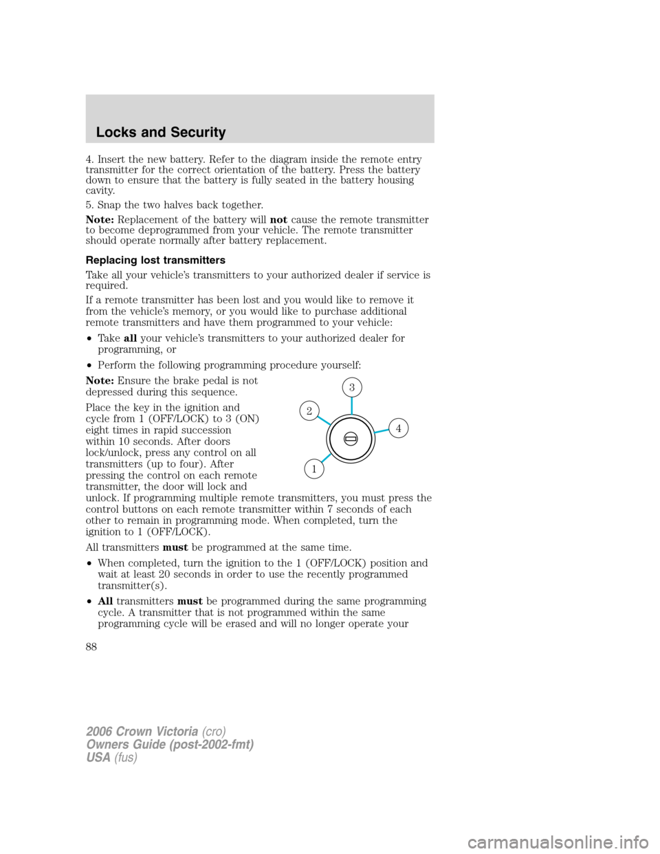
Place the key in the ignition and
cycle from 1 (OFF/LOCK) to 3 (ON)
eight times in rapid succession
within 10 seconds. After doors
lock/unlock, press any control on all
transmitters (up to four). After
pressing the control on each remote
transmitter, the door will lock and
unlock. If programming multiple remote transmitters, you must press the
control buttons on each remote transmitter within 7 seconds of each
other to remain in programming mode. When completed, turn the
ignition to 1 (OFF/LOCK).
All transmittersmustbe programmed at the same time.
•When completed, turn the ignition to the 1 (OFF/LOCK) position and
wait at least 20 seconds in order to use the recently programmed
transmitter(s).
•Alltransmittersmustbe programmed during the same programming
cycle. A transmitter that is not programmed within the same
programming cycle will be erased and will no longer operate your
4
3
2
1
2006 Crown Victoria(cro)
Owners Guide (post-2002-fmt)
USA(fus)
Locks and Security
88
Page 89 of 272
vehicle’s locks. If this occurs, you will have to reprogram all the
transmitters again, as you cannot just “add” a transmitter.
Illuminated entry
The interior lamps illuminate when the remote entry system is used to
unlock the door(s) or sound the personal alarm.
The illuminated entry system will turn off the interior lights if:
•the ignition switch is turned to the 2 (ACCESSORY), 3 (ON) or
4 (START) positions, or
•the remote transmitter lock control is pressed, or
•after 25 seconds of illumination.
The dome lamp control mustnotbe set to theoffposition for the
illuminated entry system to operate.
The inside lights will not turn off if:
•they have been turned on with the dimmer control, or
•any door is open.
The battery saver will shut off the interior lamps 30 minutes after the
last door is closed, or after 10 minutes if the last door is left open.
Autolock (if equipped)
This feature automatically locks all vehicle doors when:
•all doors are closed,
•the engine is running,
•you shift into any gear, putting the vehicle in motion, and
•the vehicle’s speed is greater than 3 mph (5 km/h).
Auto-relock
The autolock feature repeats when:
•a door is opened and closed while the engine is running,
•you shift into any gear, putting the vehicle in motion, and
•the vehicle’s speed is greater than 3 mph (5 km/h).
Auto-unlock
The auto-unlock feature will unlock all doors when:
•the ignition has been in the 3 (ON) position, all doors are closed, and
the vehicle has been in motion at a speed greater than 12 mph
(20 km/h),
2006 Crown Victoria(cro)
Owners Guide (post-2002-fmt)
USA(fus)
Locks and Security
89
Page 183 of 272
ROADSIDE ASSISTANCE
Getting roadside assistance
To fully assist you should you have a vehicle concern, Ford Motor
Company offers a complimentary roadside assistance program. This
program is separate from the New Vehicle Limited Warranty. The service
is available:
•24–hours, seven days a week
•for the New Vehicle Limited Warranty period of three years or
36,000 miles (60,000 km), whichever occurs first on Ford and Mercury
vehicles, and four years or 50,000 miles (80,000 km) on Lincoln
vehicles.
Roadside assistance will cover:
•a flat tire change with a good spare (except Ford GT which has a tire
inflation kit)
•battery jump start
•lock-out assistance (key replacement cost is the customer’s
responsibility)
•fuel delivery – Independent Service Contractors, if not prohibited by
state, local or municipal law shall deliver up to 2.0 gallons (7.5L) of
gasoline or 5 gallons (18.9L) of diesel fuel to a disabled vehicle. Fuel
delivery service is limited to two no-charge occurrences within a
12-month period.
•winch out – available within 100 feet (30.5 meters) of a paved or
county maintained road, no recoveries.
•towing – Ford/Mercury/Lincoln eligible vehicle towed to an authorized
dealer within 35 miles (56.3 km) of the disablement location or to the
nearest authorized dealer. If a member requests to be towed to an
authorized dealer more than 35 miles (56.3 km) from the disablement
location, the member shall be responsible for any mileage costs in
excess of 35 miles (56.3 km).
Trailers shall be covered up to $100 if the disabled eligible vehicle
requires service at the nearest authorized dealer. If the trailer is disabled,
but the towing vehicle is operational, the trailer does not qualify for any
roadside services.
2006 Crown Victoria(cro)
Owners Guide (post-2002-fmt)
USA(fus)
Roadside Emergencies
183
Page 190 of 272
Fuse/Relay
LocationFuse Amp
RatingPassenger Compartment Fuse
Panel Description
28 7.5A Center High-Mounted Stop Lamp
(CHMSL)
29 15A Audio
30 15A MFS, Stop lamps
31 15A Hazards (non-Police vehicles)
20A Hazards (Police vehicles)
32 10A Mirror heaters, Rear defroster
switch indicator
33 10A Ignition (ON/START), Fire
suppression module (if equipped)
(Police vehicles only)
Relay 1 Full ISO relay Rear defroster
Power distribution box
The power distribution box is located in the engine compartment. The
power distribution box contains high-current fuses that protect your
vehicle’s main electrical systems from overloads.
Always disconnect the battery before servicing high current
fuses.
To reduce risk of electrical shock, always replace the cover to
the Power Distribution Box before reconnecting the battery or
refilling fluid reservoirs.
If the battery has been disconnected and reconnected, refer to the
Batterysection of theMaintenance and Specificationschapter.
2006 Crown Victoria(cro)
Owners Guide (post-2002-fmt)
USA(fus)
Roadside Emergencies
190
Page 193 of 272
![FORD CROWN VICTORIA 2006 2.G Owners Manual Fuse/Relay
LocationFuse Amp
RatingPower Distribution Box
Description
108 20A** Moonroof (non-Police vehicles
only)
Spotlights (available on Police
vehicles, Long Wheel Base [LWB]
vehicles and commerci FORD CROWN VICTORIA 2006 2.G Owners Manual Fuse/Relay
LocationFuse Amp
RatingPower Distribution Box
Description
108 20A** Moonroof (non-Police vehicles
only)
Spotlights (available on Police
vehicles, Long Wheel Base [LWB]
vehicles and commerci](/manual-img/11/4782/w960_4782-192.png)
Fuse/Relay
LocationFuse Amp
RatingPower Distribution Box
Description
108 20A** Moonroof (non-Police vehicles
only)
Spotlights (available on Police
vehicles, Long Wheel Base [LWB]
vehicles and commercial vehicles
only)
109 20A** ABS module (Valves)
110 30A** Wiper module
111 50A** Police PDB or Police I/P accessory
battery feed (Police vehicles only)
112 30A** Air suspension compressor
(non-Police vehicles only)
40A** Police PDB relay feed (Police
vehicles only)
113 50A** Police light bar or Police Trunk
accessory battery feed (Police
vehicles only)
114 50A** Police PDB or Police I/P accessory
battery feed (Police vehicles only)
115 50A** Rear power point or Police trunk
accessory battery feed (Police
vehicles only)
116 50A** Police I/P accessory battery feed
(Police vehicles only)
117 50A** Police PDB or Police I/P accessory
battery feed (Police vehicles only)
118 50A** Rear power point or Police trunk
accessory battery feed (Police
vehicles only)
201
1�2ISO relay A/C clutch
202 — Not used
203
1�2ISO relay Ignition coil
2006 Crown Victoria(cro)
Owners Guide (post-2002-fmt)
USA(fus)
Roadside Emergencies
193
Page 201 of 272
Bolt size Wheel lug nut torque*
lb.ft. N•m
1�2x 20 100 135
* Torque specifications are for nut and bolt threads free of dirt and
rust. Use only Ford recommended replacement fasteners.
When a wheel is installed, always remove any corrosion, dirt or
foreign materials present on the mounting surfaces of the wheel
or the surface of the wheel hub, brake drum or brake disc that
contacts the wheel. Ensure that any fasteners that attach the rotor to
the hub are secured so they do not interfere with the mounting
surfaces of the wheel. Installing wheels without correct metal-to-metal
contact at the wheel mounting surfaces can cause the wheel nuts to
loosen and the wheel to come off while the vehicle is in motion,
resulting in loss of control.
JUMP STARTING
The gases around the battery can explode if exposed to flames,
sparks, or lit cigarettes. An explosion could result in injury or
vehicle damage.
Batteries contain sulfuric acid which can burn skin, eyes and
clothing, if contacted.
Do not attempt to push-start your vehicle. Automatic
transmissions do not have push-start capability; doing so may
damage the catalytic converter.
Preparing your vehicle
When the battery is disconnected or a new battery is installed, the
transmission must relearn its shift strategy. As a result, the transmission
may have firm and/or soft shifts. This operation is considered normal and
will not affect function or durability of the transmission. Over time, the
adaptive learning process will fully update transmission operation.
1.Use only a 12–volt supply to start your vehicle.
2. Do not disconnect the battery of the disabled vehicle as this could
damage the vehicle’s electrical system.
2006 Crown Victoria(cro)
Owners Guide (post-2002-fmt)
USA(fus)
Roadside Emergencies
201
Page 202 of 272
3. Park the booster vehicle close to the hood of the disabled vehicle
making sure the two vehiclesdo nottouch. Set the parking brake on
both vehicles and stay clear of the engine cooling fan and other moving
parts.
4. Check all battery terminals and remove any excessive corrosion before
you attach the battery cables. Ensure that vent caps are tight and level.
5. Turn the heater fan on in both vehicles to protect any electrical
surges. Turn all other accessories off.
Connecting the jumper cables
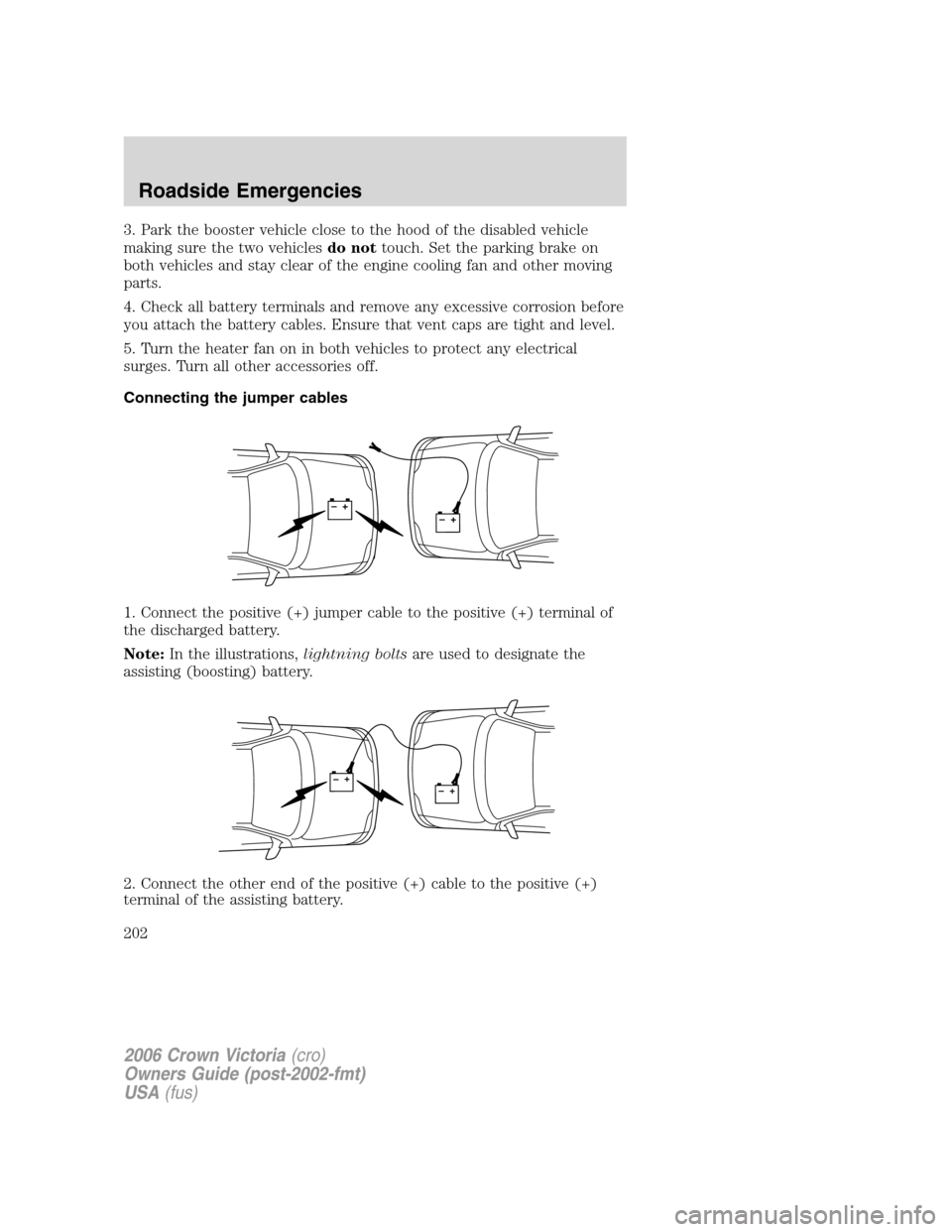
1. Connect the positive (+) jumper cable to the positive (+) terminal of
the discharged battery.
Note:In the illustrations,lightning boltsare used to designate the
assisting (boosting) battery.
2. Connect the other end of the positive (+) cable to the positive (+)
terminal of the assisting battery.
+–+–
+–+–
2006 Crown Victoria(cro)
Owners Guide (post-2002-fmt)
USA(fus)
Roadside Emergencies
202
Page 203 of 272
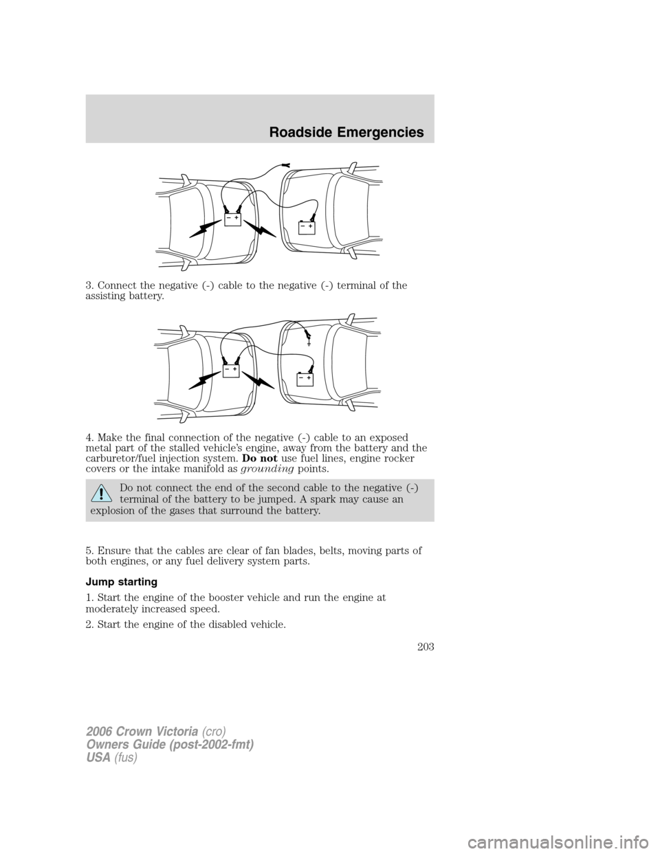
3. Connect the negative (-) cable to the negative (-) terminal of the
assisting battery.
4. Make the final connection of the negative (-) cable to an exposed
metal part of the stalled vehicle’s engine, away from the battery and the
carburetor/fuel injection system.Do notuse fuel lines, engine rocker
covers or the intake manifold asgroundingpoints.
Do not connect the end of the second cable to the negative (-)
terminal of the battery to be jumped. A spark may cause an
explosion of the gases that surround the battery.
5. Ensure that the cables are clear of fan blades, belts, moving parts of
both engines, or any fuel delivery system parts.
Jump starting
1. Start the engine of the booster vehicle and run the engine at
moderately increased speed.
2. Start the engine of the disabled vehicle.
+–+–
+–+–
2006 Crown Victoria(cro)
Owners Guide (post-2002-fmt)
USA(fus)
Roadside Emergencies
203