2006 FIAT STILO technical specifications
[x] Cancel search: technical specificationsPage 21 of 274

20
SAFETY
DEVICES
CORRECT USE
OF THE CAR
WARNING
LIGHTS AND
MESSAGES
IN AN
EMERGENCY
CAR
MAINTENANCE
TECHNICAL
SPECIFICATIONS
INDEX
DASHBOARD
AND CONTROLS
IGNITION SWITCH
The key can be turned to 3 different po-
sitions:
❒STOP: engine off, key can be removed,
steering column locked. Certain elec-
trical devices (e.g.: sound system, cen-
tral door locking, electronic alarm, etc.)
can work.
❒MAR: driving position. All electrical de-
vices are powered.
❒AVV: engine starting.
The ignition switch is fitted with a safety
mechanism that, in the event the engine is
not started, compels the driver to turn the
ignition key back to STOPbefore re-
peating the starting operation.STEERING COLUMN LOCK
Engaging
When the key is at STOPremove the
key and turn the steering wheel until it
locks.
Disengaging
Rock the steering wheel slightly as you
turn the ignition key to MAR.
fig. 17F0C0164m
If the ignition device is tam-
pered with (e.g.: attempted
theft), have it checked over by a Fiat
Dealership before restarting to drive.
WARNING
When getting out of the car,
always remove the key to
prevent any occupants from acci-
dentally activating the controls. Re-
member to engage the handbrake
and if the car is parked on uphill slope
to engage the first gear. If the car is
facing downhill, engage the reverse
gear. Never leave unsupervised chil-
dren in the car.
WARNING
It is absolutely forbidden to
carry out whatever after-
market operation involving steering
system or steering column modifica-
tions (e.g.: installation of anti-theft
device) that could badly affect per-
formance and safety, cause the lapse
of warranty and also result in non-
compliance of the car with homolo-
gation requirements.
WARNING
Never remove the ignition
key while the car is moving.
The steering wheel would automati-
cally lock as soon as you try to turn
it. This also applies when the car is
being towed.
WARNING
Page 22 of 274

21
SAFETY
DEVICES
CORRECT USE
OF THE CAR
WARNING
LIGHTS AND
MESSAGES
IN AN
EMERGENCY
CAR
MAINTENANCE
TECHNICAL
SPECIFICATIONS
INDEX
DASHBOARD
AND CONTROLS
INSTRUMENTS
REV. COUNTER fig. 18a
The rev counter shows engine rpm. The
needle pointed to the red area (danger)
indicates excessive high engine speed. Do
not drive for long periods with the needle
in this area.
IMPORTANT The electronic injection con-
trol system gradually shuts off the flow of
fuel when the engine is “over-revving” re-
sulting in a gradual loss of engine power.
When the engine is idling, the rev counter
may indicate a gradual or sudden speed in-
crease. This is normal as it takes place dur-
ing normal operation, for example when
activating the climate control system or
the fan. In particular a slow change in the
speed preserves the battery charge.
fig. 18aF0C0527mfig. 18F0C0530m
SPEEDOMETER fig. 18
It shows the car speed.
Page 23 of 274

22
SAFETY
DEVICES
CORRECT USE
OF THE CAR
WARNING
LIGHTS AND
MESSAGES
IN AN
EMERGENCY
CAR
MAINTENANCE
TECHNICAL
SPECIFICATIONS
INDEX
DASHBOARD
AND CONTROLS
If the needle reaches the red
area, stop the engine immedi-
ately and contact a Fiat Deal-
ership.
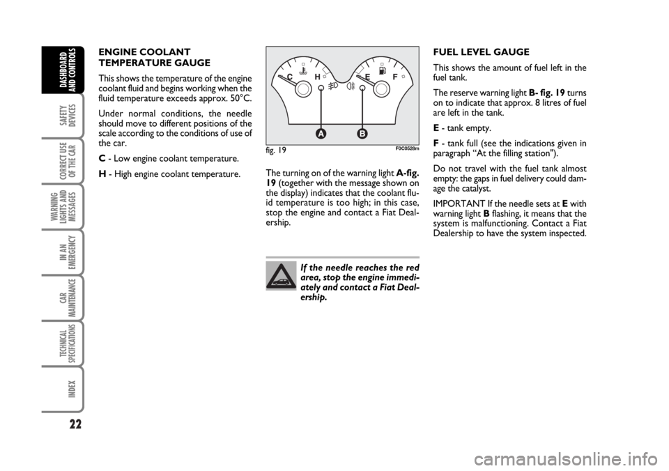
fig. 19F0C0528m
ENGINE COOLANT
TEMPERATURE GAUGE
This shows the temperature of the engine
coolant fluid and begins working when the
fluid temperature exceeds approx. 50°C.
Under normal conditions, the needle
should move to different positions of the
scale according to the conditions of use of
the car.
C- Low engine coolant temperature.
H- High engine coolant temperature.FUEL LEVEL GAUGE
This shows the amount of fuel left in the
fuel tank.
The reserve warning light B- fig. 19turns
on to indicate that approx. 8 litres of fuel
are left in the tank.
E- tank empty.
F- tank full (see the indications given in
paragraph “At the filling station").
Do not travel with the fuel tank almost
empty: the gaps in fuel delivery could dam-
age the catalyst.
IMPORTANT If the needle sets at Ewith
warning light Bflashing, it means that the
system is malfunctioning. Contact a Fiat
Dealership to have the system inspected. The turning on of the warning light A-fig.
19(together with the message shown on
the display) indicates that the coolant flu-
id temperature is too high; in this case,
stop the engine and contact a Fiat Deal-
ership.
Page 24 of 274

23
SAFETY
DEVICES
CORRECT USE
OF THE CAR
WARNING
LIGHTS AND
MESSAGES
IN AN
EMERGENCY
CAR
MAINTENANCE
TECHNICAL
SPECIFICATIONS
INDEX
DASHBOARD
AND CONTROLS
MULTIFUNCTION
DISPLAY
Your car is fitted with the multifunction
display that shows all the useful informa-
tion necessary when driving.
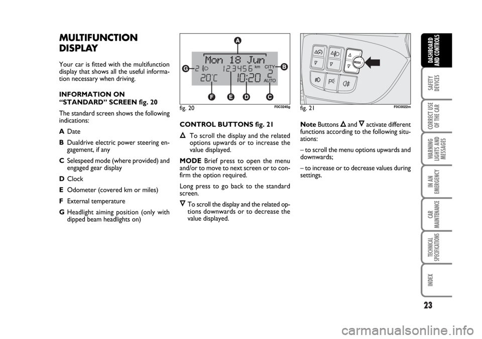
INFORMATION ON
“STANDARD” SCREEN fig. 20
The standard screen shows the following
indications:
ADate
BDualdrive electric power steering en-
gagement, if any
CSelespeed mode (where provided) and
engaged gear display
DClock
EOdometer (covered km or miles)
FExternal temperature
GHeadlight aiming position (only with
dipped beam headlights on) CONTROL BUTTONS fig. 21
ÕTo scroll the display and the related
options upwards or to increase the
value displayed.
MODEBrief press to open the menu
and/or to move to next screen or to con-
firm the option required.
Long press to go back to the standard
screen.
ÔTo scroll the display and the related op-
tions downwards or to decrease the
value displayed.NoteButtons
Õand Ôactivate different
functions according to the following situ-
ations:
– to scroll the menu options upwards and
downwards;
– to increase or to decrease values during
settings.
fig. 21F0C0022mfig. 20F0C3245g
Page 25 of 274

24
SAFETY
DEVICES
CORRECT USE
OF THE CAR
WARNING
LIGHTS AND
MESSAGES
IN AN
EMERGENCY
CAR
MAINTENANCE
TECHNICAL
SPECIFICATIONS
INDEX
DASHBOARD
AND CONTROLS
SETUP MENU fig. 22
The menu comprises a series of functions
arranged in a “circular fashion” which can
be selected through buttons
Õand Ôto
access the different select operations and
settings (setup) given below. For certain
options (Set time and Units) there is a sub-
menu.
The setup menu can be activated by press-
ing briefly button MODE.
Single presses on buttons
Õor Ôwill
scroll the setup menu options. Handling
modes differ with each other according to
the characteristic of the option selected.
NoteIf the car is equipped with Con-
nect/Navigator, phone and audio info can
be repeated on the multifunction display.
For other set-up menu adjustments and/or
settings, see the Connect/Navigator Sup-
plement.Selecting an option in the main menu
without submenu:
– press briefly button MODEto select
the menu option to set;
– press buttons
Õor Ô(by single press-
es) to select the new setting;
– press briefly button MODEto store the
new setting and to go back to the previ-
ously selected menu option.Selecting an option in the main menu with
submenu:
– press briefly button MODEto display
the first submenu option;
– press buttons Õor Ô(by single press-
es) to scroll all submenu options;
– press briefly button MODEto select
the displayed submenu option and to en-
ter the relevant setup menu;
– press buttons
Õor Ô(by single press-
es) to select the new setting;
– press briefly button MODEto store the
new setting and to go back to the previ-
ously selected submenu option.
Page 26 of 274

25
SAFETY
DEVICES
CORRECT USE
OF THE CAR
WARNING
LIGHTS AND
MESSAGES
IN AN
EMERGENCY
CAR
MAINTENANCE
TECHNICAL
SPECIFICATIONS
INDEX
DASHBOARD
AND CONTROLS
Selecting “Set date” and “Set time”:
– briefly press button MODEto select
the first value to change (e.g. hours /min-
utes or year / month / day);
– press buttons
Õor Ô(by single press-
es) to select the new setting;
– briefly press button MODEto store the
new setting and to go to the next setup
menu option, if this is the last one you will
go back to the previously selected option
of the main menu.Press button MODE for long:
– to quit the submenu if you are at sub-
menu option setting level;
– to quit the main menu if you are at sub-
menu level;
– to quit the main menu if you are at main
menu option setting level;
– to quit the set up menu if you are in the
main menu;
– only settings stored yet by the user (and
confirmed by pressing briefly button
MODE) will be saved.The setup menu displaying is timed; when
quitting the menu due to timing expiry,
only settings stored yet by the user (and
confirmed by pressing briefly button
MODE) will be saved.
Page 27 of 274

26
SAFETY
DEVICES
CORRECT USE
OF THE CAR
WARNING
LIGHTS AND
MESSAGES
IN AN
EMERGENCY
CAR
MAINTENANCE
TECHNICAL
SPECIFICATIONS
INDEX
DASHBOARD
AND CONTROLS
Day
YearMonth
Español
English
Portuges
Deutsch
Français
Italiano
EXIT MENUTRIP B DATASET TIME
SET DATE
SEE RADIO
KEY
AUTOCLOSE
UNITS
LANGUAGE
BUZZER VOLUME BUTTON VOL. BELT BUZZER SERVICESPEED BEEP
Briefly press button MODEto start surfing from the standard
screen. To surf the menu use buttons Õor Ô. For safety rea-
sons, when the car is running, it is possible to access only the
reduced menu (for setting the “Speed limit” and “Automatic
headlight sensor sensitivity adjustment” (where provided).
When the car is stationary access to the whole menu is en-
abled. On cars provided with Connect/Navigator many func-
tions are displayed on the navigator display.
MODE
briefly press
button
MODE
briefly press
button
Example:
fig. 22
HEADL. SENSOR
F0C2369g
Page 28 of 274

27
SAFETY
DEVICES
CORRECT USE
OF THE CAR
WARNING
LIGHTS AND
MESSAGES
IN AN
EMERGENCY
CAR
MAINTENANCE
TECHNICAL
SPECIFICATIONS
INDEX
DASHBOARD
AND CONTROLS
Speed limit (Speed Beep)
With this function it is possible to set the
car speed limit (km/h or mph); when this
limit is exceeded the driver is immediate-
ly alerted (see section “Warning lights and
messages”).
To set the speed limit, proceed as follows:
– briefly press button MODE, the display
will show wording (Speed Beep);
– press button
Õor Ôto select activa-
tion (On) or deactivation (Off) of the
speed limit;
– if selecting (On), press button
Õor Ôto select the required speed limit and then
press MODEto confirm.
NoteThe possible setting is between 30
and 250 km/h, or between 20 and 155
mph depending on the unit set previous-
ly (see paragraph “Distance unit (Dis-
tances)” described later. Every press on
button
Õ/Ôincreases/decreases by 5
units. Keeping the button Õ/Ôpressed
obtains the automatic fast increase or de-
crease. When you are near the required
setting complete adjustment by single
presses.
– briefly press button MODEto go back
to the menu screen or press the button
for long to go back to the standard screen
without storing settings.To abort the setting, proceed as follows:
– briefly press button MODE: (On) will
flash on the display;
– press button
Ô: (Off) will flash on the
display;
– briefly press button MODEto go back
to the menu screen or press the button
for long to go back to the standard screen
without storing settings.Automatic headlight sensor
sensitivity adjustment
(Headl. sensor) (where provided)
With this function it is possible to adjust
the light sensor sensitivity according to 3
levels (level 1 = min. level, level 2 = av-
erage level, level 3 = max. level); the high-
er the sensitivity is, the lower is the ex-
ternal light intensity required to switch on
the lights.
This operation can be performed also with
the car moving.
To set the light level required, proceed as
follows:
– briefly press button MODE, the previ-
ously set level will flash on the display;
– press button
Õor Ôto select the re-
quired level;
– briefly press button MODEto go back
to the menu screen or press the button
for long to go back to the standard screen
without storing settings.