Page 157 of 238

156
WARNING
LIGHTS AND
MESSAGES
VEHICLE
MAINTENANCE
TECHNICAL
SPECIFICATIONS
IINDEX
DASHBOARD
AND CONTROLS
SAFETY
DEVICES
CORRECT USE
OF THE
VEHICLE
IN AN
EMERGENCY
THIRD BRAKE LIGHT fig. 31-32
To change the bulb proceed as follows:
❒loosen the two fastening screws A-
fig. 31;
❒remove the lens unit;
❒press the tabs B-fig. 32and remove
the bulb holder;
❒remove the snap-fitted bulb and re-
place it.NUMBER PLATE LIGHT fig. 33
To change the bulb proceed as follows:
❒work in the point shown by the arrow
and remove the lens unit A;
❒change the bulb releasing it from the
side contacts and making sure the new
bulb is correctly fastened between the
contacts;
❒refit the snap-fitted lens unit.
IF AN INTERIOR LIGHT
BURNS OUT
For the type of bulb and power rating, see
“When needing to change a bulb”.
FRONT CEILING LIGHT
To replace the bulbs proceed as follows:
❒work in the points shown by the ar-
rows and remove light A-fig. 34;
❒open the protection lid B-fig. 35;
❒replace bulbs C-fig. 35releasing them
from the side contacts; make sure that
new bulbs are correctly clamped be-
tween contacts;
❒re-close the lid B-fig. 35and secure
light A-fig. 34into its housing lock-
ing it properly.
fig. 32F0N0142m
fig. 33F0N0089mfig. 31F0N0141m
Page 158 of 238

157
WARNING
LIGHTS AND
MESSAGES
VEHICLE
MAINTENANCE
TECHNICAL
SPECIFICATIONS
INDEX
DASHBOARD
AND CONTROLS
SAFETY
DEVICES
CORRECT USE
OF THE
VEHICLE
IN AN
EMERGENCY
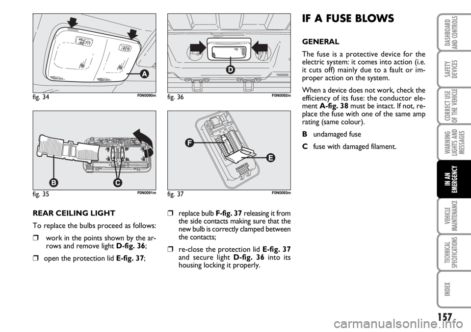
REAR CEILING LIGHT
To replace the bulbs proceed as follows:
❒work in the points shown by the ar-
rows and remove light D-fig. 36;
❒open the protection lid E-fig. 37;
❒replace bulb F-fig. 37releasing it from
the side contacts making sure that the
new bulb is correctly clamped between
the contacts;
❒re-close the protection lid E-fig. 37
and secure light D-fig. 36into its
housing locking it properly.
fig. 34F0N0090m
fig. 35F0N0091m
fig. 36F0N0092m
fig. 37F0N0093m
IF A FUSE BLOWS
GENERAL
The fuse is a protective device for the
electric system: it comes into action (i.e.
it cuts off) mainly due to a fault or im-
proper action on the system.
When a device does not work, check the
efficiency of its fuse: the conductor ele-
ment A-fig. 38must be intact. If not, re-
place the fuse with one of the same amp
rating (same colour).
Bundamaged fuse
Cfuse with damaged filament.
Page 159 of 238
158
WARNING
LIGHTS AND
MESSAGES
VEHICLE
MAINTENANCE
TECHNICAL
SPECIFICATIONS
IINDEX
DASHBOARD
AND CONTROLS
SAFETY
DEVICES
CORRECT USE
OF THE
VEHICLE
IN AN
EMERGENCY
fig. 38F0N0094m
Never change a fuse with
another with a higher amp
rating, DANGER OF FIRE.
WARNING
Never replace a broken fuse
with anything other than a
new fuse.
If a general fuse (MEGA-
FUSE, MIDI-FUSE, MAXI-
FUSE) cuts in, do not attempt any re-
pair and contact Fiat Dealership. Be-
fore changing a fuse, check the igni-
tion key has been removed and that
all the other electric devices have
been turned off/disabled.
WARNING
If a fuse blows again, contact
a Fiat Dealership.
WARNING
Page 160 of 238
159
WARNING
LIGHTS AND
MESSAGES
VEHICLE
MAINTENANCE
TECHNICAL
SPECIFICATIONS
INDEX
DASHBOARD
AND CONTROLS
SAFETY
DEVICES
CORRECT USE
OF THE
VEHICLE
IN AN
EMERGENCY
FUSE LOCATION
Fuses are grouped into three fuse boxes
to be found respectively on the dashboard,
on the passenger compartment right pil-
lar and in the engine compartment.
Fuse box on the
dashboard
To gain access to the fuses in the fuse box
on the dashboard, loosen the fastening
screws A-fig. 39and remove the cover.
fig. 40F0N0096m
fig. 39F0N0095m
Page 161 of 238
160
WARNING
LIGHTS AND
MESSAGES
VEHICLE
MAINTENANCE
TECHNICAL
SPECIFICATIONS
IINDEX
DASHBOARD
AND CONTROLS
SAFETY
DEVICES
CORRECT USE
OF THE
VEHICLE
IN AN
EMERGENCY
fig. 42F0N0097m
fig. 41F0N0098m
Fuse box in engine compartment
To gain access to the fuse box, remove the
protection cover fig. 41.
Page 162 of 238
161
WARNING
LIGHTS AND
MESSAGES
VEHICLE
MAINTENANCE
TECHNICAL
SPECIFICATIONS
INDEX
DASHBOARD
AND CONTROLS
SAFETY
DEVICES
CORRECT USE
OF THE
VEHICLE
IN AN
EMERGENCY
Optional fuse box on the right cen-
tral post (where provided)
To gain access to the fuse box, remove the
protection cover fig. 43.
fig. 43F0N0172m
fig. 44F0N0171m
Page 163 of 238

162
WARNING
LIGHTS AND
MESSAGES
VEHICLE
MAINTENANCE
TECHNICAL
SPECIFICATIONS
IINDEX
DASHBOARD
AND CONTROLS
SAFETY
DEVICES
CORRECT USE
OF THE
VEHICLE
IN AN
EMERGENCY
FUSE SUMMARY TABLE
Fuse box on dashboard
USERSFUSE AMPERE
Right dipped beam headlight F12 7.5
Left dipped beam headlight, Headlight aiming device F13 7.5
Engine compartment fuse box relay, dashboard fuse box relay (+key) F31 7.5
Minibus internal lights (emergency) F32 10
Rear current outlet F33 15
AbsentF34 –
Reversing lights, sevotronic control unit, Water in diesel fuel filter sensor, (+key) F35 7.5
Central door locking (+ battery) F36 20
Brake lights (main), Third brake light, Instrument panel (+key) F37 10
Dashboard control unit relay (+ battery) F38 10
EOBD socket, Sound System, A/C control, Alarm, Chronotachograph,
Webasto timer (+battery) F39 10
Left-hand heated window, Driver’s mirror defroster F40 15
Right-hand heated window, Passenger’s mirror defroster F41 15
ABS, ASR, ESP, Brake light control (secondary) (+key) F42 7.5
Windscreen wiper (+key) F43 30
Cigar lighter, Front current outlet F44 20
Page 164 of 238
163
WARNING
LIGHTS AND
MESSAGES
VEHICLE
MAINTENANCE
TECHNICAL
SPECIFICATIONS
INDEX
DASHBOARD
AND CONTROLS
SAFETY
DEVICES
CORRECT USE
OF THE
VEHICLE
IN AN
EMERGENCY
USERSFUSE AMPERE
Control on driver’s door, Controls on passenger’s door F45 7.5
AbsentF46 –
Driver’s power window F47 20
Passenger’s power window F48 20
Sound System, Driver’s power window, Dashboard controls,
Alarm control unit, Rain sensor (+key) F49 7.5
Airbag (+key)F50 7.5
A/C control, Cruise control, Chronotachograph (+key) F51 7.5
Optional fuse box relay F52 7.5
Instrument panel, Rear fog lights (+battery) F53 7.5