Page 448 of 536

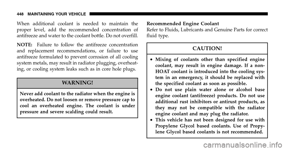
When additional coolant is needed to maintain the
proper level, add the recommended concentration of
antifreeze and water to the coolant bottle. Do not overfill.
NOTE: Failure to follow the antifreeze concentration
and replacement recommendations, or failure to use
antifreeze formulated to prevent corrosion of all cooling
system metals, may result in radiator plugging, overheat-
ing, or cooling system leaks such as in core hole plugs.
WARNING!
Never add coolant to the radiator when the engine is
overheated. Do not loosen or remove pressure cap to
cool an overheated engine. The coolant is under
pressure and severe scalding could result.
Recommended Engine Coolant
Refer to Fluids, Lubricants and Genuine Parts for correct
fluid type.
CAUTION!
•Mixing of coolants other than specified engine
coolant, may result in engine damage. If a non-
HOAT coolant is introduced into the cooling sys-
tem in an emergency, it should be replaced with
the specified coolant as soon as possible.
•Do not use plain water alone or alcohol base
engine coolant (antifreeze) products. Do not use
additional rust inhibitors or antirust products, as
they may not be compatible with the radiator
engine coolant and may plug the radiator.
•This vehicle has not been designed for use with
Propylene Glycol based coolants. Use of Propy-
lene Glycol based coolants is not recommended.
448 MAINTAINING YOUR VEHICLE
Page 449 of 536

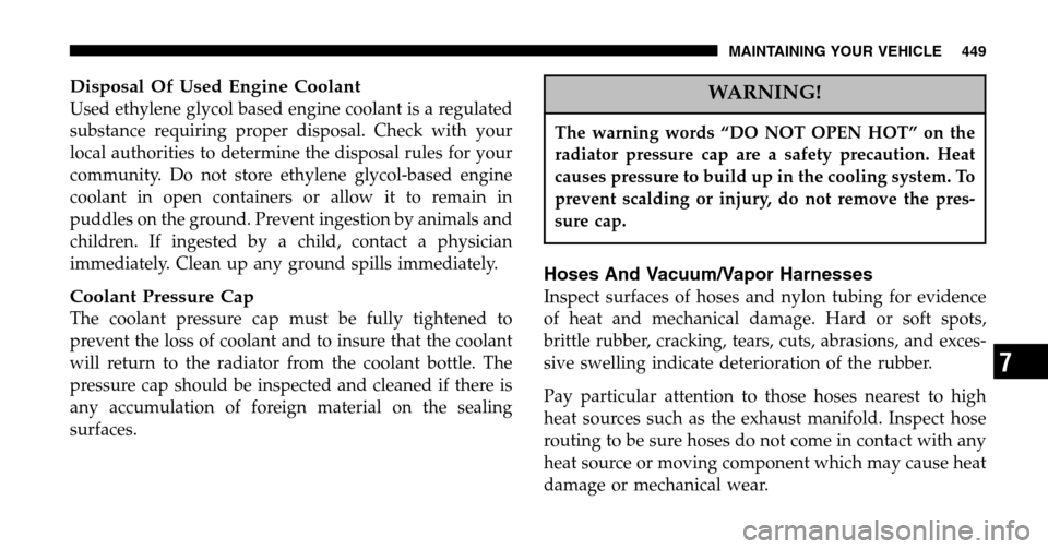
Disposal Of Used Engine Coolant
Used ethylene glycol based engine coolant is a regulated
substance requiring proper disposal. Check with your
local authorities to determine the disposal rules for your
community. Do not store ethylene glycol-based engine
coolant in open containers or allow it to remain in
puddles on the ground. Prevent ingestion by animals and
children. If ingested by a child, contact a physician
immediately. Clean up any ground spills immediately.
Coolant Pressure Cap
The coolant pressure cap must be fully tightened to
prevent the loss of coolant and to insure that the coolant
will return to the radiator from the coolant bottle. The
pressure cap should be inspected and cleaned if there is
any accumulation of foreign material on the sealing
surfaces.
WARNING!
The warning words “DO NOT OPEN HOT” on the
radiator pressure cap are a safety precaution. Heat
causes pressure to build up in the cooling system. To
prevent scalding or injury, do not remove the pres-
sure cap.
Hoses And Vacuum/Vapor Harnesses
Inspect surfaces of hoses and nylon tubing for evidence
of heat and mechanical damage. Hard or soft spots,
brittle rubber, cracking, tears, cuts, abrasions, and exces-
sive swelling indicate deterioration of the rubber.
Pay particular attention to those hoses nearest to high
heat sources such as the exhaust manifold. Inspect hose
routing to be sure hoses do not come in contact with any
heat source or moving component which may cause heat
damage or mechanical wear.
MAINTAINING YOUR VEHICLE 449
7
Page 451 of 536

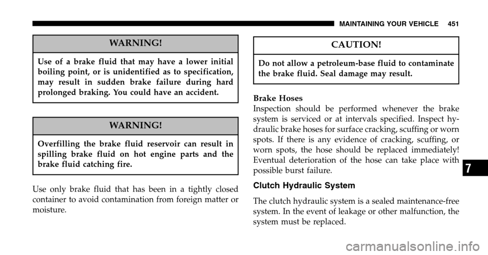
WARNING!
Use of a brake fluid that may have a lower initial
boiling point, or is unidentified as to specification,
may result in sudden brake failure during hard
prolonged braking. You could have an accident.
WARNING!
Overfilling the brake fluid reservoir can result in
spilling brake fluid on hot engine parts and the
brake fluid catching fire.
Use only brake fluid that has been in a tightly closed
container to avoid contamination from foreign matter or
moisture.
CAUTION!
Do not allow a petroleum-base fluid to contaminate
the brake fluid. Seal damage may result.
Brake Hoses
Inspection should be performed whenever the brake
system is serviced or at intervals specified. Inspect hy-
draulic brake hoses for surface cracking, scuffing or worn
spots. If there is any evidence of cracking, scuffing, or
worn spots, the hose should be replaced immediately!
Eventual deterioration of the hose can take place with
possible burst failure.
Clutch Hydraulic System
The clutch hydraulic system is a sealed maintenance-free
system. In the event of leakage or other malfunction, the
system must be replaced.
MAINTAINING YOUR VEHICLE 451
7
Page 454 of 536

Lubricant Selection G56 (6-Speed Manual
Transmission — If Equipped)
This transmission is filled with manual transmission
fluid at the factory. This fluid does not require periodic
changing. If it is necessary to add or change fluid in this
transmission refer to Fluids, Lubricants and Genuine
Parts for correct fluid type. This is the only lubricant
recommended for use in the Getrag G56 transmission.
Automatic Transmission
Fluid Level Check
The fluid level should be checked when the engine is
fully warmed up and the fluid in the transmission is at
normal operating temperature. Operation of the trans-
mission with an improper fluid level will greatly reduce
the life of the transmission and of the fluid. Check the
fluid level whenever the vehicle is serviced.
Fluid Level Check – 45RFE/545RFE/42RLE
Check the fluid level while the transmission is at normal
operating temperature 82°C (180°F). This occurs after at
least 15 miles (25 km) of driving. At normal operating
temperature the fluid cannot be held comfortably be-
tween the fingertips.
To check the automatic transmission fluid level properly,
the following procedure must be used:
1. Operate the engine at idle speed and normal operating
temperature.
2. The vehicle must be on level ground.
3. Fully apply the parking brake and press the brake
pedal.
4. Place the gear selector momentarily in each gear
position ending with the lever in P (Park).
454 MAINTAINING YOUR VEHICLE
Page 459 of 536

should be performed anytime a malfunction is observed
or suspected. Proper maintenance of the entire vehicle
will help the effectiveness of the noise control systems.
Air Cleaner Assembly
Inspect air cleaner housing for proper assembly and fit.
Make certain that the air cleaner is properly positioned
and the cover is tight. Check all hoses leading to the
cleaner for tightness. The gasket between the air cleaner
housing and throttle body must be intact and in good
condition. The engine air cleaner filter must also be clean
and serviced according to the instructions outlined in the
appropriate maintenance schedule.
Tampering with Noise Control System Prohibited
Federal law prohibits the following acts or the causing
thereof: (1) the removal or rendering inoperative by any
person, other than for purposes of maintenance, repair, or
replacement, of any device or element of design incorpo-
rated into any new vehicle for the purpose of noise control prior to its sale or delivery to the ultimate
purchaser or while it is in use, or (2) the use of the vehicle
after such device or element of design has been removed
or rendered inoperative by any person.
Among those acts presumed to constitute tampering are
the acts listed below.
AIR CLEANER
•Removal of the air cleaner.
•Inverting the air cleaner lid.
•Removal of the air ducting.
EXHAUST SYSTEM
•Removal or rendering inoperative exhaust system
components including the muffler or tailpipe.
MAINTAINING YOUR VEHICLE 459
7
Page 460 of 536
ENGINE COOLING SYSTEM
•Removal or rendering inoperative the fan clutch.
•Removal of the fan shroud.
Noise Emission Warranty
The manufacturer warrants that this vehicle as manufac-
tured by the manufacturer, was designed, built and
equipped to conform at the time it left the manufacturers
control with all applicable U.S. EPA Noise Control Regu-
lations. This warranty covers this vehicle as designed, built and
equipped by the manufacturer, and is not limited to any
particular part, component or system of the vehicle
manufactured by the manufacturer. Defects in design,
assembly or in any part, component or system of the
vehicle as manufactured by the manufacturer, which, at
the time it left the manufacturers control, caused noise
emissions to exceed Federal standards, are covered by
this warranty for the life of the vehicle.
460 MAINTAINING YOUR VEHICLE
Page 466 of 536
INTEGRATED POWER MODULE
An integrated Power Module is located in the engine
compartment near the battery. This center contains car-
tridge fuses and mini fuses. A description of each fuse
and component may be stamped on the inside cover otherwise the cavity number of each fuse is stamped on
the inside cover that corresponds to the following chart.
Cavity Cartridge
Fuse Mini
Fuse Description
1 20 Amp Yellow Power Outlet Console
2 20 Amp Yellow CCN Door Locks/
BTSI
3 20 Amp Yellow Spare
4 20 Amp Yellow Spare
5 20 Amp Yellow Power Sunroof
6 10 Amp Red OCM/VIST Fan/
Wastegate
7 15 Amp Blue Reverse Lockout Sole-
noid Battery (SRT-10
Only)
Integrated Power Module Location
466 MAINTAINING YOUR VEHICLE
Page 467 of 536
Cavity Cartridge Fuse Mini
Fuse Description
8 10 Amp Red Heated Mirrors
9 30 Amp Pink Off Road Module
Power
10 5 Amp Orange Trx-Off Rd Pkg Sen
(Gas Engine Only)
11 20 Amp Yellow IOD-CNN/Radio/
Under Hood Lamp/
WCM/SDARS/HFM
12 30 Amp Pink Electric Brake
13 25 Amp Natural Power-Battery
RWAL/ABS Module
Feed
14 15 Amp Blue Park Lamps LeftCavity Cartridge
Fuse Mini
Fuse Description
15 20 Amp Yellow Trailer Park Lamps
16 15 Amp Blue Park Lamps Right
17 15 Amp Blue Spare
18 40 Amp Green ABS Pump
19 30 Amp Pink Trailer Tow
20 10 Amp Red ORC2
21 10 Amp Red ORC Preset Carrier
22 2 Amp Gray IGN Switch Feed
MAINTAINING YOUR VEHICLE 467
7