Page 101 of 302

Power Switch, Volume Control
Press the ON/VOL control to turn the radio on. Turn the
volume control clockwise to increase the volume. The
volume will be displayed and continuously updated
while the button is pressed.
Seek Button (Radio Mode)
Press and release the Seek button to search for the next
station in either the AM or FM mode. Press the top of the
button to seek up and the bottom to seek down. Holding
the button will by pass stations until you release the
button.
Tuning
Press the TUNE control up or down to increase or
decrease the frequency. If you press and hold the button,
the radio will continue to tune until you release the
button. The frequency will be displayed and continu-
ously updated while the button is pressed.
Radio Data System (RDS)
The Radio Data System allows radio broadcasting sta-
tions to send data signals on a subcarrier frequency
which is added to the stereo signal. RDS was developed
to give FM receivers user-friendly features, such as
Program Service name (PS) and Program Type (PTY).
Program Service name is typically used by the broad-
caster to display the station’s name or call letters, for
example�WNIC�. Typically these are 8 characters in
length and are displayed by the radio for those stations
which are broadcasting this information. PTY (Program
Type) is used to characterize the station’s program ma-
terial, for example�Rock Music�.
PTY (Program Type) Button
Pressing this button once will turn on the PTY mode for
5 seconds. If no action is taken during the 5 second time
out the PTY icon will turn off. Pressing the PTY button
within 5 seconds will allow the program format type to
be selected. Many radio stations do not currently broad-
cast PTY information.
UNDERSTANDING YOUR INSTRUMENT PANEL 101
4
Page 193 of 302
Towing Requirements — Trailer Lights & Wiring
Whenever you pull a trailer, regardless of the trailer size,
stop lights and turn signals on the trailer are required for
motoring safety.
The Trailer Tow Package may includea4and7pin
wiring harness. Use a factory approved trailer harness
and connector.
NOTE:Do not cut or splice wiring into the vehicles
wiring harness.
The electrical connections are all complete to the vehicle
but you must mate the harness to a trailer connector.
Refer to the following illustrations.
4 - Pin Connector
STARTING AND OPERATING 193
5
Page 198 of 302

HAZARD WARNING FLASHER
The flasher switch is on top of the steering column,
just behind the steering wheel. Depress the switch
and both cluster indicators and all front and rear direc-
tional signals will flash. Depress the switch again to turn
Hazard Warning Flashers off.
Do not use this emergency warning system when the
vehicle is in motion. Use it when your vehicle is disabled
and is creating a safety hazard for other motorists.If it is necessary to leave the vehicle to go for service, the
flasher system will continue to operate with the ignition
key removed and the vehicle locked.
NOTE:With extended use, the flasher may wear down
your battery.
IF YOUR ENGINE OVERHEATS
In any of the following situations, you can reduce the
potential for overheating by taking the appropriate ac-
tion.
•On the highways — Slow down.
•In city traffic — While stopped, put transaxle in
neutral, but do not increase engine idle speed.
NOTE:There are steps that you can take to slow down
an impending overheat condition. If your air conditioner
is on, turn it off. The air conditioning system adds heat to
the engine cooling system and turning off the A/C
removes this heat. You can also turn the Temperature
control to maximum heat, the Mode control to floor, and
the fan control to High. This allows the heater core to act
as a supplement to the radiator and aids in removing heat
from the engine cooling system.
Hazard Flasher Switch
198 WHAT TO DO IN EMERGENCIES
Page 212 of 302

▫Appearance Care And Protection From
Corrosion...........................241
�Convertible Top Care...................246
▫Washing............................246
▫General Cleaning.....................246
▫Cloth Top Additional Cleaning Procedure....247
▫Cloth Top Protection...................247
▫Weather Strip Care....................247
�Fuses...............................248
▫Underhood Fuses
(Power Distribution Center)..............248
▫Interior Fuses........................248
�Vehicle Storage........................250
�Replacement Light Bulbs................251
�Bulb Replacement......................251
▫Headlight Bulb Replacement.............251
▫Park, Turn Signal, Sidemarker Bulb
Replacement.........................253
▫Fog Light Bulb Replacement.............255
▫Center Stoplight Bulb Replacement.........255
▫Rear Light Bulb Replacement.............256
▫License Plate Bulb Replacement...........257
▫Headlight Aiming.....................257
�Fluids And Capacities...................257
�Fluids, Lubricants And Genuine Parts.......258
▫Engine.............................258
▫Chassis............................259
212 MAINTAINING YOUR VEHICLE
Page 250 of 302

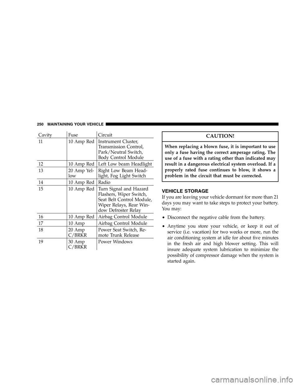
Cavity Fuse Circuit
11 10 Amp Red Instrument Cluster,
Transmission Control,
Park/Neutral Switch,
Body Control Module
12 10 Amp Red Left Low beam Headlight
13 20 Amp Yel-
lowRight Low Beam Head-
light, Fog Light Switch
14 10 Amp Red Radio
15 10 Amp Red Turn Signal and Hazard
Flashers, Wiper Switch,
Seat Belt Control Module,
Wiper Relays, Rear Win-
dow Defroster Relay
16 10 Amp Red Airbag Control Module
17 10 Amp Airbag Control Module
18 20 Amp
C/BRKRPower Seat Switch, Re-
mote Trunk Release
19 30 Amp
C/BRKRPower WindowsCAUTION!
When replacing a blown fuse, it is important to use
only a fuse having the correct amperage rating. The
use of a fuse with a rating other than indicated may
result in a dangerous electrical system overload. If a
properly rated fuse continues to blow, it shows a
problem in the circuit that must be corrected.
VEHICLE STORAGE
If you are leaving your vehicle dormant for more than 21
days you may want to take steps to protect your battery.
You may:
•Disconnect the negative cable from the battery.
•Anytime you store your vehicle, or keep it out of
service (i.e. vacation) for two weeks or more, run the
air conditioning system at idle for about five minutes
in the fresh air and high blower setting. This will
insure adequate system lubrication to minimize the
possibility of compressor damage when the system is
started again.
250 MAINTAINING YOUR VEHICLE
Page 251 of 302

REPLACEMENT LIGHT BULBS
LIGHT BULBS — Interior Bulb Number
Instrument Cluster..................... PC194
ABS Indicator........................ PC161
Fog Indicators........................ PC161
Floor Console, Courtesy Light, Door Courtesy Light,
Trunk Light............................ 562
Climate Control Light...................... 37
Traction Control Light...................PC161
LIGHT BULBS — Exterior Bulb Number
Headlight.............................9007
Park/Turn Signal (Front).................3157A
Side/Marker (Front)...................... 168
Turn Signal (Rear)......................3757A
Fog Light.............................880L
Center Stop Light (CHMSL)......Dealer Service Item
Tail/Stop.............................3157
Tail Light.........................W3W/2821
Back Up Light.....................W16W/921
License Light......................W5W/2825
BULB REPLACEMENT
Headlight Bulb Replacement
1. Open the hood and remove the two headlight mount-
ing screws.
2. Remove the push-in fasteners by prying under the
head of the fasteners with a flat bladed tool.
MAINTAINING YOUR VEHICLE 251
7
Page 253 of 302
5. Pull the bulb out of the socket and replace the bulb.
CAUTION!
Do not touch the new bulb with your fingers. Oil
contamination will severely shorten bulb life.
6. If the bulb comes in contact with any oily surface,
clean the bulb with rubbing alcohol.
7. Reinsert the bulb and socket assembly and turn the
retaining ring clockwise to secure the bulb.
8. Reinstall the headlight assembly.
Park, Turn Signal, Sidemarker Bulb Replacement
1. Open the hood and remove the two headlight assem-
bly mounting screws. Pull the headlight assembly away
from the vehicle.
MAINTAINING YOUR VEHICLE 253
7
Page 292 of 302

Cooling............................ 232
Exhaust Gas Caution.................. 180
Fails to Start......................... 148
Fuel Requirements.................178,257
Oil ..........................218,257,258
Oil Change Interval................... 219
Oil Selection......................220,257
Oil Synthetic......................... 221
Overheating......................... 198
Timing Belt.......................... 224
Engine Oil Viscosity..................... 257
Entry System, Illuminated................. 12
Exhaust Gas Caution...............43,180,231
Exhaust System........................ 231
Exterior Light Service.................... 251
Filters
Air Cleaner.......................... 222
Automatic Transaxle................... 240
Engine Fuel......................... 223
Engine Oil.......................221,258
Engine Oil Disposal................... 221Flashers
Hazard Warning...................... 198
Turn Signal.......................... 90
Flash-To-Pass........................... 69
Flat Tire Changing...................... 199
Flexible Fuel Vehicles
Cruising Range....................... 182
Engine Oil.......................... 182
Fuel Requirements.................181,182
Maintenance......................... 183
Replacement Parts.................... 183
Starting............................ 182
Floor Console.......................... 55
Fluid, Brake........................... 259
Fluid Capacities........................ 257
Fluid Leaks............................ 44
Fluid Level Checks
Automatic Transaxle................... 240
Capacities........................... 257
Cooling System....................... 232
Engine Oil.......................... 218
Power Steering....................... 227
Fluids............................... 258
292 INDEX