Page 331 of 426

Windshield Wiper Blade
Replacement
Windshield wiper blades should be inspected for wear
and cracking. SeeScheduled Maintenance on page 6-4
for more information.
Replacement blades come in different types and are
removed in different ways. For the proper type and
length, seeNormal Maintenance Replacement Parts on
page 6-14.
It is a good idea to clean or replace the wiper blade
assembly every six months.
Allowing the wiper blade arm to touch the windshield
when no wiper blade is installed could damage the
windshield. Any damage that occurs would not be
covered by your warranty. Do not allow the wiper blade
arm to touch the windshield.
To remove the wiper blade assembly, do the following:
1. Open the hood to gain access to the windshield
wipers.
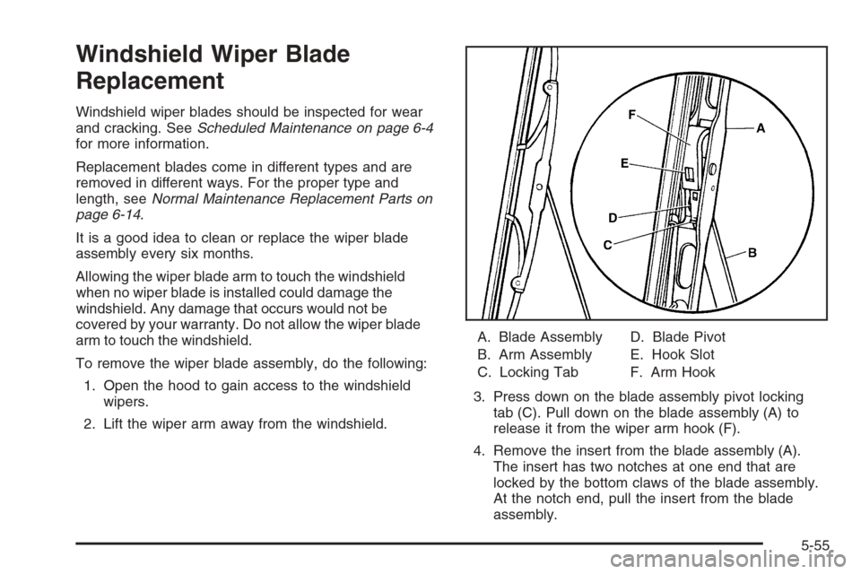
2. Lift the wiper arm away from the windshield.A. Blade Assembly
B. Arm Assembly
C. Locking TabD. Blade Pivot
E. Hook Slot
F. Arm Hook
3. Press down on the blade assembly pivot locking
tab (C). Pull down on the blade assembly (A) to
release it from the wiper arm hook (F).
4. Remove the insert from the blade assembly (A).
The insert has two notches at one end that are
locked by the bottom claws of the blade assembly.
At the notch end, pull the insert from the blade
assembly.
5-55
Page 332 of 426
To install the new wiper insert:
1. Slide the insert (D), notched end last, into the end
with the two blade claws (A). Slide the insert all the
way through the blade claws at the opposite end (B).
Plastic caps (C) will be forced off as the insert is fully
installed.
2. Be sure the notches are locked by the bottom
claws. Make sure that all other claws are properly
locked on both sides of the insert slots.3. Put the blade assembly pivot in the wiper arm hook.
Pull up until the pivot locking tab locks in the
hook slot.
4. Carefully lower the wiper arm and blade assembly
onto the windshield.
Installation guide:
A. Claw in Notch
B. Correct Installation
C. Incorrect Installation
5-56
Page 347 of 426

If you must replace your vehicle’s tires with those that do
not have a TPC Spec number, make sure they are the
same size, load range, speed rating, and construction
type (radial and bias-belted tires) as your vehicle’s
original tires.
Vehicles that have a tire pressure monitoring system
may give an inaccurate low-pressure warning if non-TPC
spec rated tires are installed on your vehicle. Non-TPC
Spec rated tires may give a low-pressure warning
that is higher or lower than the proper warning level
you would get with TPC Spec rated tires. SeeTire
Pressure Monitor System on page 5-67.
Your vehicle’s original equipment tires are listed on the
Tire and Loading Information Label. This label is
attached to the vehicle’s center pillar (B-pillar).
SeeLoading Your Vehicle on page 4-33for more
information about the Tire and Loading Information Label
and its location on your vehicle.Different Size Tires and Wheels
If you add wheels or tires that are a different size than
your original equipment wheels and tires, this may
affect the way your vehicle performs, including its
braking, ride and handling characteristics, stability, and
resistance to rollover. Additionally, if your vehicle
has electronic systems such as, anti-lock brakes,
traction control, and electronic stability control, the
performance of these systems can be affected.
{CAUTION:
If you add different sized wheels, your vehicle
may not provide an acceptable level of
performance and safety if tires not
recommended for those wheels are selected.
You may increase the chance that you will
crash and suffer serious injury. Only use
GM speci�c wheel and tire systems developed
for your vehicle, and have them properly
installed by a GM certi�ed technician.
SeeBuying New Tires on page 5-70andAccessories
and Modi�cations on page 5-3for additional information.
5-71
Page 352 of 426

Tire Chains
{CAUTION:
Do not use tire chains. There is not enough
clearance. Tire chains used on a vehicle
without the proper amount of clearance can
cause damage to the brakes, suspension, or
other vehicle parts. The area damaged by the
tire chains could cause you to lose control of
your vehicle and you or others may be injured
in a crash. Use another type of traction device
only if its manufacturer recommends it for use
on your vehicle and tire size combination and
road conditions. Follow that manufacturer’s
instructions. To help avoid damage to your
vehicle, drive slowly, re-adjust or remove the
device if it is contacting your vehicle, and
do not spin your wheels. If you do �nd
traction devices that will �t, install them on
the rear tires.
Lifting Your Vehicle
{CAUTION:
Lifting a vehicle can cause an injury. The
vehicle can slip off the jack and roll over you
or other people. You and they could be badly
injured. Find a level place to lift your vehicle.
To help prevent the vehicle from moving:
1. Set the parking brake �rmly.
2. Put an automatic transmission shift lever in
PARK (P), or shift a manual transmission to
FIRST (1) or REVERSE (R).
3. Turn off the engine.
To be even more certain the vehicle won’t move,
you can put blocks in front of and behind the
wheels.
5-76
Page 353 of 426

{CAUTION:
Getting under a vehicle when it is jacked up is
dangerous. If the vehicle slips off the jack, you
could be badly injured or killed. Never get under
a vehicle when it is supported only by a jack.
{CAUTION:
Raising your vehicle with the jack improperly
positioned can damage the vehicle and even
make the vehicle fall. To help avoid personal
injury and vehicle damage, be sure to place
the jack in the proper location before raising
the vehicle.If you ever use a jack to lift your vehicle, follow the
instructions that came with the jack, and be sure to use
the correct lifting points to avoid damaging your vehicle.
Notice:Lifting your vehicle improperly can damage
your vehicle and result in costly repairs not covered
by your warranty. To lift your vehicle properly, follow
the advice in this part.
To help prevent vehicle damage:
Be sure to place a block or pad between the
jack and the vehicle.
Make sure the jack you’re using spans at least
two crossmember ribs.
Lift only in the areas shown in the following
pictures.
For additional information, see your dealer and the
Chevrolet Corvette service manual.
5-77
Page 354 of 426
Lifting From the Front
The front lifting points can be accessed from either side
of your vehicle, behind the front tires.
1. Locate the front lifting points (A), according to the
illustration shown.
2. Be sure to place a block or pad between the jack
and the vehicle.
5-78
Page 356 of 426
1. Locate the rear lifting points (A), according to the
illustration shown.
2. Be sure to place a block or pad between the jack
and the vehicle.3. Lift the vehicle with the jack, making sure the jack
spans at least two of the crossmember ribs (B).
For more information, seeDoing Your Own Service
Work on page 5-4.
5-80
Page 370 of 426
Instrument Panel Fuse Block
The instrument panel fuse block is located on the passenger’s side of the vehicle, under the instrument panel and
under the toe-board.
Remove the carpet and toe-board covering to access the fuse block by pulling at the top of each corner of the panel.
Open the fuse block cover to access the fuses.
You can remove fuses using the fuse puller.
5-94