Page 13 of 24
13
DSC - NEW FUNCTIONS
AUTOMATIC DIFFERENTIAL BRAKE (ADB)
On dry pavement with no wheel slip, the vehicle’s driving torque is split 68% rear and 32%
front through the planetary gear differential transfer case.
If one or more wheels spin or slip, the DSC will activate a regulation process and the brakes
on the effected wheel(s) will be pulsed. The driving torque will be distributed through the dif-
ferential to the remaining wheels with a good coefficient of friction
The driving torque will be applied through the differential as follows:
• Three wheels - with one wheel spinning.
• On two diagonal wheels with two wheels spinning on different axles.
• One axle only with two wheels spinning on the same axle.
Once the spin or slip is under control, the drive torque will again be applied to all wheels.
Page 15 of 24

15
DSC - NEW FEATURE
TRACTION CONTROL
The traction control feature of the DSC III on the X5 cannot be switched OFF with the DSC
switch. Pressing the button will only switch off the dynamic stability control function of the
DSC.
The traction control feature is needed at all times to provide anti-spin control especially
when driving the vehicle off road. The DSC warning lamp in the instrument cluster will still
come on when the system is switched off manually or there is a fault in the system.
Off road traction control or HDC regulation places an additional load on the brakes. To pre-
vent overheating of the brakes and rotors, the temperature of the rotors is calculated over
time from the road speed and amount of brake application. If the temperature of one or
more rotors goes above 600o
C, the traction control or HDC function for that wheel will be
cancelled temporarily. Once the temperature of the rotor goes below 500o
C, the traction
application will be re-activated.
The normal braking function (including ABS) is always active at any temperatures.
DSC - NEW FEATURE
OFF-ROAD ABS Control Module Programming
The programming for ABS regulation have changed to allow a higher threshold for ABS reg-
ulation when driving off-road in loose gravel or dirt. A locked wheel is more effective in slow-
ing or stopping the vehicle because of the wedge that is built up in front of the tire.
The programming in the DSC control module allows one or both front wheel(s) to lock up
to a speed of 12 MPH as long as the vehicle is traveling straight ahead. If the DSC control
module receives a signal from the steering angle sensor indicating a turn, ABS regulation
will activate to prevent the lock and allow the vehicle to be steered.
Page 21 of 24

21
DSC III COMPONENTS
HDC SWITCH
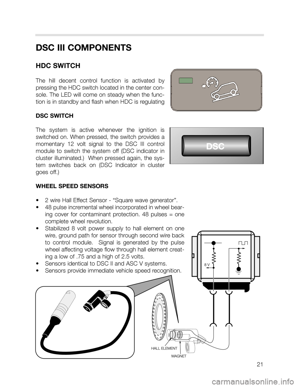
The hill decent control function is activated by
pressing the HDC switch located in the center con-
sole. The LED will come on steady when the func-
tion is in standby and flash when HDC is regulating
DSC SWITCH
The system is active whenever the ignition is
switched on. When pressed, the switch provides a
momentary 12 volt signal to the DSC III control
module to switch the system off (DSC indicator in
cluster illuminated.) When pressed again, the sys-
tem switches back on (DSC Indicator in cluster
goes off.)
WHEEL SPEED SENSORS
• 2 wire Hall Effect Sensor - “Square wave generator”.
• 48 pulse incremental wheel incorporated in wheel bear-
ing cover for contaminant protection. 48 pulses = one
complete wheel revolution.
• Stabilized 8 volt power supply to hall element on one
wire, ground path for sensor through second wire back
to control module. Signal is generated by the pulse
wheel affecting voltage flow through hall element creat-
ing a low of .75 and a high of 2.5 volts.
• Sensors identical to DSC II and ASC V systems.
• Sensors provide immediate vehicle speed recognition.
Page 22 of 24

STEERING ANGLE SENSOR
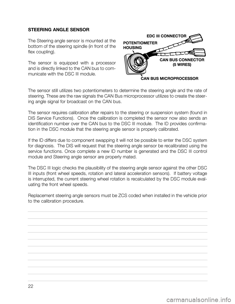
The Steering angle sensor is mounted at the
bottom of the steering spindle (in front of the
flex coupling).
The sensor is equipped with a processor
and is directly linked to the CAN bus to com-
municate with the DSC III module.
The sensor still utilizes two potentiometers to determine the steering angle and the rate of
steering. These are the raw signals the CAN Bus microprocessor utilizes to create the steer-
ing angle signal for broadcast on the CAN bus.
The sensor requires calibration after repairs to the steering or suspension system (found in
DIS Service Functions). Once the calibration is completed the sensor now also sends an
identification number over the CAN bus to the DSC III module. The ID provides confirma-
tion in the DSC module that the steering angle sensor is properly calibrated.
If the ID differs due to component swapping it will not be possible to enter the DSC system
for diagnosis. The DIS will request that the steering angle sensor be recalibrated using the
service functions. Once complete a new ID number is generated and the DSC III control
module and Steering angle sensor are properly mated.
The DSC III logic checks the plausibility of the steering angle sensor against the other DSC
III inputs (front wheel speeds, rotation and lateral acceleration sensors). If battery voltage
is interrupted, the current steering wheel rotation is recalculated by the DSC module eval-
uating the front wheel speeds.
Replacement steering angle sensors must be ZCS coded when installed in the vehicle prior
to the calibration procedure.
22
Page 24 of 24
24
DIAGNOSIS
Diagnosis and troubleshooting of the DSC III system is carried out using the DIS Tester or
MoDiC. The DSC control module performs a self check every time the ignition is switched
on. The warning lamps for DSC and ABS will remain on during the self check.
Any faults with the system will cause the lamps to remain on when the engine is started.
Faults that only effect the DSC operation will cause the DSC warning lamp to remain on,
however ABS can still function.
If the battery has been disconnected, the DSC warning lamp will remain on until the vehi-
cle receives road speed signals front the front wheel speed sensors and the steering angle
sensor can calculate the direction of travel.