Page 4 of 163
Table of ContentsYou can also consult the in-
dex at the end of this Rider's
Manual if you want to find a
particular topic or item of in-
formation.
1 General instructions . . . 5
Overview . ................ 6
Abbreviations and
symbols . . . ............... 6
Equipment ............... 7
Technical data ........... 7
Currency . . ............... 7
2 General views . . . . . .... 9
General view, left side . . . 11
General view, right
side ..................... 13
Underneath the seat . . . . . 14
Handlebar fitting, left . . . . . 15
Handlebar fitting, right . . . 16
Instrument cluster . . . . . . . 17
Headlight . .............. 18 3 Status indicators . . . . . 19
Multifunction display . . . . . 20
Warning and telltale
lights . . . . .
.............. 20
ABS warning light . . . . . . . 20
Function indicators . . . . . . 20
Warnings, general . . . . . . . 21
Warnings issued by the
tyre pressure monitoring
system (RDC)
OE
......... 29
ABS warnings . .......... 33
4 Operation . . . .......... 37
Ignition switch and
steering lock . . .......... 38
Electronic immobiliser . . . 39
Hazard warning
flashers . . . .............. 40
Odometer and
tripmeters . .............. 41
Clock . . . . . .............. 42
Tyre pressure control
RDC
OE
.................. 44
On-board computer
OE
... 44 Emergency off switch (kill
switch) . . . .
.............. 48
Grip heating
OE
........... 48
Clutch . . . . .............. 49
Brakes . . . . .............. 49
Lights . . . . . .............. 50
Headlight . .............. 51
Turn indicators .......... 52
Seat . . . . . . .............. 53
Helmet holder . .......... 55
Luggage loops .......... 56
Mirrors . . . . .............. 56
Spring preload .......... 56
Shock absorbers . . . . . . . . 57
Electronic Suspension
Adjustment ESAOE
....... 59
Tyres . . . . . .............. 60
5 Riding . . .............. 63
Safety instructions . . . . . . . 64
Checklist . . .............. 66
Starting . . . .............. 66
Running in .............. 68
Page 9 of 163
ESA Electronic SuspensionAdjustment
Electronic Suspension
Adjustment.
DWA Anti-theft alarm (Diebs-
tahlwarnanlage)
ABS Anti-lock brake system
RDC Tyre pressure control
(ReifenDruck-Control)EquipmentWhen you ordered your BMW
motorcycle, you chose vari-
ous items of custom equip-
ment. This Rider's Manual
describes optional extras (OE)
offered by BMW and selec-
ted optional accessories (OA).
This explains why the manual
may also contain descriptions
of equipment which you have
not ordered. Please note, too,
that your motorcycle might not be exactly as illustrated
in this manual on account of
country-specific differences.
If your BMW was supplied
with equipment not described
in this Rider's Manual, you will
find these features described
in separate manuals.
Technical dataAll dimensions, weights and
power ratings stated in the
Rider's Manual are quoted
to the standards and comply
with the tolerance require-
ments of the Deutsche Institut
für Normung e.V. (DIN). Ver-
sions for individual countries
may differ.CurrencyThe high safety and quality
standards of BMW motor-
cycles are maintained by con-
stant development work on
designs, equipment and ac-cessories. Because of this,
your motorcycle may differ
from the information supplied
in the Rider's Manual. Nor
can errors and omissions be
entirely ruled out. We hope
you will appreciate that no
claims can be entertained on
the basis of the data, illustra-
tions or descriptions in this
manual.
17zGeneral instructions
Page 39 of 163
Operation
Ignition switch and steering
lock . . . . . . . . . . . . . . . . . . . . . . . . . . . 38
Electronic immobiliser . . . . . . . . . 39
Hazard warning flashers . . . . . . . 40
Odometer and tripmeters . . . . . . 41
Clock . . . . . . . . . . . . . . . . . . . . . . . . . 42
Tyre pressure control RDC
OE
.. 44
On-board computer
OE
......... 44
Emergency off switch (kill
switch) . . . . . . . . . . . . . . . . . . . . . . . . 48
Grip heating
OE
................ 48
Clutch . . . . . . . . . . . . . . . . . . . . . . . . 49
Brakes . . . . . . . . . . . . . . . . . . . . . . . . 49
Lights . . . . . . . . . . . . . . . . . . . . . . . . . 50
Headlight . . . . . . . . . . . . . . . . . . . . . 51
Turn indicators . . . . . . . . . . . . . . . . 52 Seat . . . . . . . . . . . . . . . . . . . . . . . . . . 53
Helmet holder . . . . . . . . . . . . . . . . . 55
Luggage loops . . . . . . . . . . . . . . . . 56
Mirrors . . . . . . . . . . . . . . . . . . . . . . . . 56
Spring preload . . . . . . . . . . . . . . . . 56
Shock absorbers . . . . . . . . . . . . . . 57
Electronic Suspension
Adjustment ESA
OE
............ 59
Tyres . . . . . . . . . . . . . . . . . . . . . . . . . 60
437zOperation
Page 60 of 163
Adjusting rear shock
absorber
Your motorcycle's hand-
ling will suffer if you do
not match the spring-preload
and damping-characteristic
settings.
Adjust the damping
characteristic to suit spring
preload.
Make sure the ground is
level and firm and place the
motorcycle on its stand. Adjust the rear shock ab-
sorber, using a screwdriver
to turn adjusting screw
1.
If you want a harder damp-
ing characteristic, use a
screwdriver to turn adjust- ing screw
1in the direction
indicated by the H arrow.
If you want a softer damp-
ing characteristic, use a
screwdriver to turn adjust-
ing screw 1in the direction
indicated by the S arrow.
The adjusting screw can
be turned through three
and a half turns.
Rear suspension
damping, basic setting
Turn the adjusting screw
as far as it will go in the
direction indicated by the
H arrow and then turn it
back one and a half turns
in the direction indicated
by the S arrow. (One-up
85 kg)
458zOperation
Page 61 of 163
Electronic Suspension
Adjustment ESA
OE
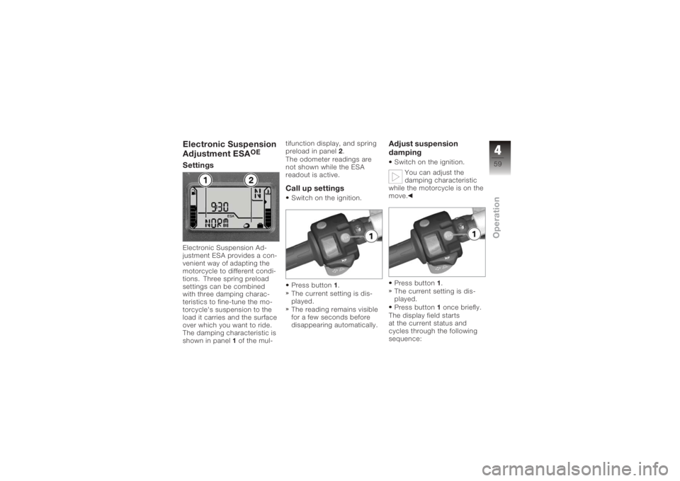
SettingsElectronic Suspension Ad-
justment ESA provides a con-
venient way of adapting the
motorcycle to different condi-
tions. Three spring preload
settings can be combined
with three damping charac-
teristics to fine-tune the mo-
torcycle's suspension to the
load it carries and the surface
over which you want to ride.
The damping characteristic is
shown in panel1of the mul- tifunction display, and spring
preload in panel
2.
The odometer readings are
not shown while the ESA
readout is active.
Call up settingsSwitch on the ignition.
Press button 1.
The current setting is dis-
played.
The reading remains visible
for a few seconds before
disappearing automatically.
Adjust suspension
dampingSwitch on the ignition.
You can adjust the
damping characteristic
while the motorcycle is on the
move.
Press button 1.
The current setting is dis-
played.
Press button 1once briefly.
The display field starts
at the current status and
cycles through the following
sequence:
459zOperation
Page 101 of 163
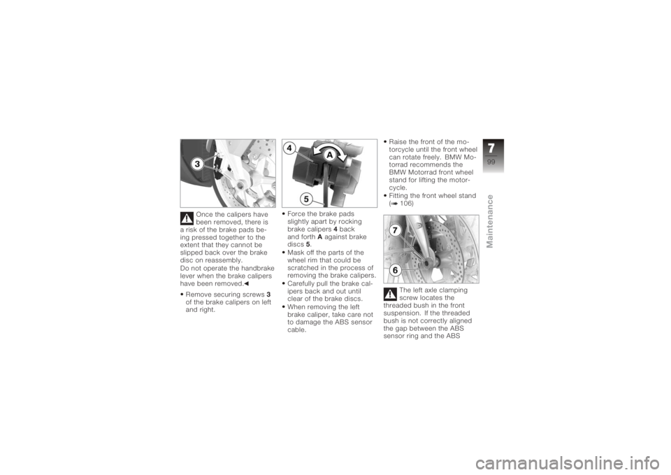
Once the calipers have
been removed, there is
a risk of the brake pads be-
ing pressed together to the
extent that they cannot be
slipped back over the brake
disc on reassembly.
Do not operate the handbrake
lever when the brake calipers
have been removed.
Remove securing screws 3
of the brake calipers on left
and right. Force the brake pads
slightly apart by rocking
brake calipers
4back
and forth Aagainst brake
discs 5.
Mask off the parts of the
wheel rim that could be
scratched in the process of
removing the brake calipers.
Carefully pull the brake cal-
ipers back and out until
clear of the brake discs.
When removing the left
brake caliper, take care not
to damage the ABS sensor
cable. Raise the front of the mo-
torcycle until the front wheel
can rotate freely. BMW Mo-
torrad recommends the
BMW Motorrad front wheel
stand for lifting the motor-
cycle.
Fitting the front wheel stand
( 106)
The left axle clamping
screw locates the
threaded bush in the front
suspension. If the threaded
bush is not correctly aligned
the gap between the ABS
sensor ring and the ABS
799zMaintenance
Page 108 of 163
front wheel with the BMW
Motorrad front-wheel stand.Fitting the front wheel
standPlace the motorcycle on an
auxiliary stand; BMW Motor-
rad recommends the BMW
Motorrad rear-wheel stand.
Fitting the rear wheel stand
( 107)
with OA Centre stand:
Make sure the ground is
level and firm and place
the motorcycle on its centre
stand. Slacken adjusting screws
1.
Push the two pins 2apart
until the front suspension
fits between them.
Use locating pins 3to set
the front wheel stand to the
desired height.
Centre the front-wheel
stand relative to the front
wheel and push it against
the front axle. Push both mounting pins
2
through the triangles of the
brake caliper anchorages
just far enough to allow
the front wheel to be rolled
between them.
There is a risk of dam-
aging the ABS sensor
ring of the BMW Integral ABS.
Push the pin in just far
enough to ensure that it
clears the sensor ring of the
BMW Integral ABS.
Tighten adjusting screws 1.
7106zMaintenance
Page 141 of 163
Final driveFinal drive, typeShaft drive with bevel gears
Final drive gear ratio 2.82Running gearFront suspensionDouble leading link
Front suspension - total suspension travel 115 mm, Static 125 mm, Dynamic
Rear suspension type Central spring strut pivoted to lever system
with coil spring and single-tube gas-filled
shock absorber; spring preload steplessly
hydraulically adjustable, rebound stage
damping steplessly adjustable.
with OE Electronic Suspension Adjust-
ment (ESA): Central spring strut pivoted to lever system
with coil spring and single-tube gas-filled
shock absorber; spring basic setting three-
way adjustable, compression and rebound
stages each three-way adjustable
Rear suspension, total suspension travel 135 mm, at wheel
9139zTechnical data