2006 BMW MOTORRAD K 1200 S brake light
[x] Cancel search: brake lightPage 4 of 163
Table of ContentsYou can also consult the in-
dex at the end of this Rider's
Manual if you want to find a
particular topic or item of in-
formation.
1 General instructions . . . 5
Overview . ................ 6
Abbreviations and
symbols . . . ............... 6
Equipment ............... 7
Technical data ........... 7
Currency . . ............... 7
2 General views . . . . . .... 9
General view, left side . . . 11
General view, right
side ..................... 13
Underneath the seat . . . . . 14
Handlebar fitting, left . . . . . 15
Handlebar fitting, right . . . 16
Instrument cluster . . . . . . . 17
Headlight . .............. 18 3 Status indicators . . . . . 19
Multifunction display . . . . . 20
Warning and telltale
lights . . . . .
.............. 20
ABS warning light . . . . . . . 20
Function indicators . . . . . . 20
Warnings, general . . . . . . . 21
Warnings issued by the
tyre pressure monitoring
system (RDC)
OE
......... 29
ABS warnings . .......... 33
4 Operation . . . .......... 37
Ignition switch and
steering lock . . .......... 38
Electronic immobiliser . . . 39
Hazard warning
flashers . . . .............. 40
Odometer and
tripmeters . .............. 41
Clock . . . . . .............. 42
Tyre pressure control
RDC
OE
.................. 44
On-board computer
OE
... 44 Emergency off switch (kill
switch) . . . .
.............. 48
Grip heating
OE
........... 48
Clutch . . . . .............. 49
Brakes . . . . .............. 49
Lights . . . . . .............. 50
Headlight . .............. 51
Turn indicators .......... 52
Seat . . . . . . .............. 53
Helmet holder . .......... 55
Luggage loops .......... 56
Mirrors . . . . .............. 56
Spring preload .......... 56
Shock absorbers . . . . . . . . 57
Electronic Suspension
Adjustment ESAOE
....... 59
Tyres . . . . . .............. 60
5 Riding . . .............. 63
Safety instructions . . . . . . . 64
Checklist . . .............. 66
Starting . . . .............. 66
Running in .............. 68
Page 29 of 163
Rear light bulb defectiveGeneral warning light
lights up yellow.
The
LAMPR!
warning ap-
pears on the display.
A defective bulb places
your safety at risk be-
cause it is easier for other
users to oversee you and
your motorcycle.
Replace defective bulbs as
soon as possible; always
carry a complete set of spare
bulbs if possible.
Rear light or brake light bulb
defective.
Replacing brake light and
rear light bulb ( 113)
Front light bulb defective
The
LAMPF!
warning ap-
pears on the display. A defective bulb places
your safety at risk be-
cause it is easier for other
users to oversee you and
your motorcycle.
Replace defective bulbs as
soon as possible; always
carry a complete set of spare
bulbs if possible.
Low-beam headlight, high-
beam headlight, side-light or
turn-indicator bulb defective.
Replacing low-beam head-
light bulb ( 109)
Replacing high-beam head-
light bulb ( 111)
Replacing parking-light bulb
( 113)
Replacing front turn indicat-
or bulbs ( 115)
Replacing rear turn indicator
bulbs ( 117) Bulbs defective
General warning light
lights up yellow.
The
LAMPS!
warning ap-
pears on the display.
A defective bulb places
your safety at risk be-
cause it is easier for other
users to oversee you and
your motorcycle.
Replace defective bulbs as
soon as possible; always
carry a complete set of spare
bulbs if possible.
A combination of the bulb de-
fects described above has
occurred.
See the fault descriptions
above.
Ice warning Ice warning symbol ap-
pears on the display.
327zStatus indicators
Page 39 of 163
Operation
Ignition switch and steering
lock . . . . . . . . . . . . . . . . . . . . . . . . . . . 38
Electronic immobiliser . . . . . . . . . 39
Hazard warning flashers . . . . . . . 40
Odometer and tripmeters . . . . . . 41
Clock . . . . . . . . . . . . . . . . . . . . . . . . . 42
Tyre pressure control RDC
OE
.. 44
On-board computer
OE
......... 44
Emergency off switch (kill
switch) . . . . . . . . . . . . . . . . . . . . . . . . 48
Grip heating
OE
................ 48
Clutch . . . . . . . . . . . . . . . . . . . . . . . . 49
Brakes . . . . . . . . . . . . . . . . . . . . . . . . 49
Lights . . . . . . . . . . . . . . . . . . . . . . . . . 50
Headlight . . . . . . . . . . . . . . . . . . . . . 51
Turn indicators . . . . . . . . . . . . . . . . 52 Seat . . . . . . . . . . . . . . . . . . . . . . . . . . 53
Helmet holder . . . . . . . . . . . . . . . . . 55
Luggage loops . . . . . . . . . . . . . . . . 56
Mirrors . . . . . . . . . . . . . . . . . . . . . . . . 56
Spring preload . . . . . . . . . . . . . . . . 56
Shock absorbers . . . . . . . . . . . . . . 57
Electronic Suspension
Adjustment ESA
OE
............ 59
Tyres . . . . . . . . . . . . . . . . . . . . . . . . . 60
437zOperation
Page 52 of 163
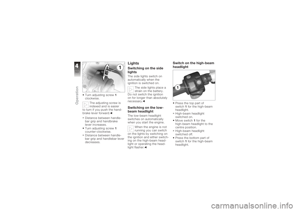
Turn adjusting screw1
clockwise.
The adjusting screw is
indexed and is easier
to turn if you push the hand-
brake lever forward.
Distance between handle-
bar grip and handbrake
lever increases.
Turn adjusting screw 1
counter-clockwise.
Distance between handle-
bar grip and handlebar lever
decreases.
LightsSwitching on the side
lightsThe side lights switch on
automatically when the
ignition is switched on.
The side lights place a
strain on the battery.
Do not switch the ignition
on for longer than absolutely
necessary.Switching on the low-
beam headlightThe low-beam headlight
switches on automatically
when you start the engine.
When the engine is not
running you can switch
on the lights by switching on
the ignition and either switch-
ing on the high-beam head-
light or operating the head-
light flasher.
Switch on the high-beam
headlightPress the top part of
switch 1for the high-beam
headlight.
High-beam headlight
switched on.
Move switch 1for the
high-beam headlight to the
centre position.
High-beam headlight
switched off.
Press the bottom part of
switch 1for the high-beam
headlight.
450zOperation
Page 68 of 163
ponents are not designed to
withstand. Damage caused in
this way is not covered by the
warranty.
Do not tamper with the
control unit of the electronic
engine-management
system.ChecklistUse the following checklist
to check important functions,
settings and wear limits be-
fore you ride off.Brakes
Brake-fluid levels, front and
rear
Clutch
Clutch fluid level
Shock absorber setting and
spring preload
Tyre-tread depth and tyre
pressures Cases correctly installed
and luggage secured
At regular intervals: Engine oil level (every refuel-
ling stop)
Brake-pad wear (every third
refuelling stop)
StartingSide standYou cannot start the motor-
cycle with the side stand ex-
tended and a gear engaged.
The engine will switch itself off
if you start it with the gearbox
in neutral and then engage a
gear before retracting the side
stand.GearboxYou can start the engine
when the gearbox is in neutral
or if you pull the clutch with
a gear engaged. Do not pull
the clutch until after you have switched on the ignition, as
otherwise the engine will
refuse to start. When the
gearbox is in neutral, the
green neutral telltale light is
on and the gear indicator
in the multifunction display
shows N.
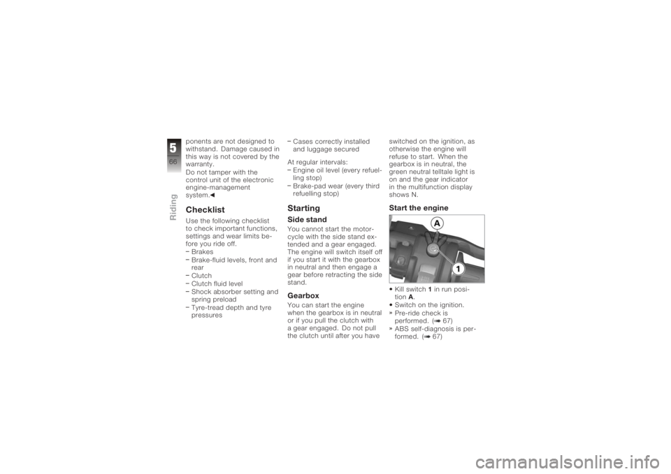
Start the engineKill switch
1in run posi-
tion A.
Switch on the ignition.
Pre-ride check is
performed. ( 67)
ABS self-diagnosis is per-
formed. ( 67)
566zRiding
Page 101 of 163
Once the calipers have
been removed, there is
a risk of the brake pads be-
ing pressed together to the
extent that they cannot be
slipped back over the brake
disc on reassembly.
Do not operate the handbrake
lever when the brake calipers
have been removed.
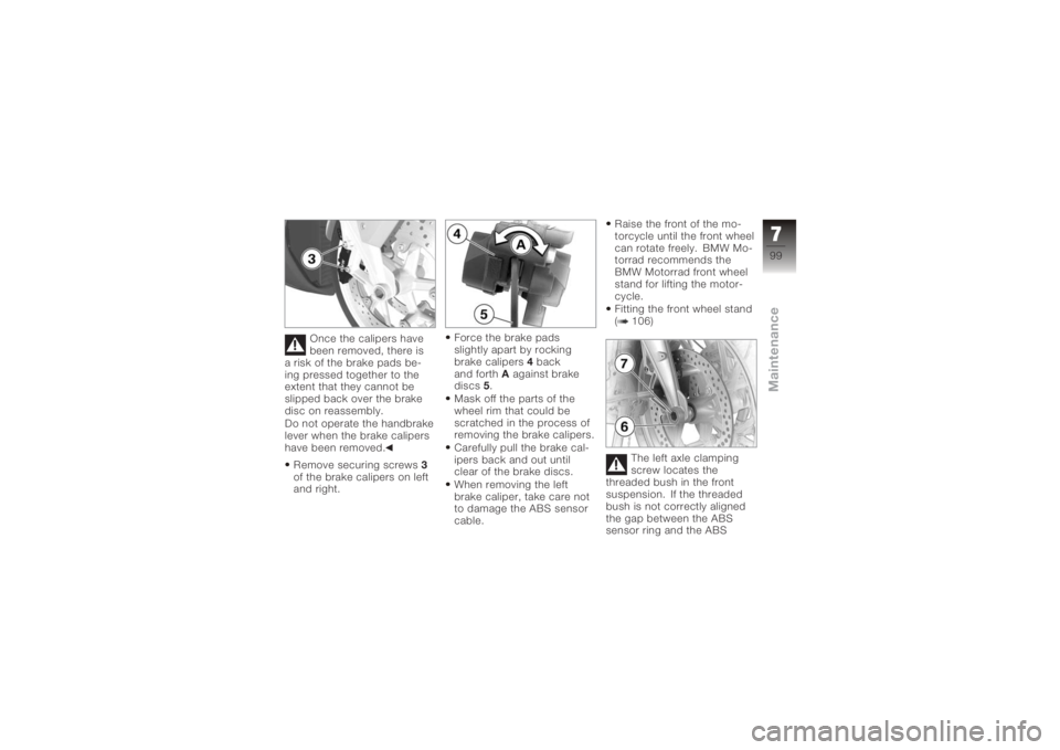
Remove securing screws 3
of the brake calipers on left
and right. Force the brake pads
slightly apart by rocking
brake calipers
4back
and forth Aagainst brake
discs 5.
Mask off the parts of the
wheel rim that could be
scratched in the process of
removing the brake calipers.
Carefully pull the brake cal-
ipers back and out until
clear of the brake discs.
When removing the left
brake caliper, take care not
to damage the ABS sensor
cable. Raise the front of the mo-
torcycle until the front wheel
can rotate freely. BMW Mo-
torrad recommends the
BMW Motorrad front wheel
stand for lifting the motor-
cycle.
Fitting the front wheel stand
( 106)
The left axle clamping
screw locates the
threaded bush in the front
suspension. If the threaded
bush is not correctly aligned
the gap between the ABS
sensor ring and the ABS
799zMaintenance
Page 110 of 163
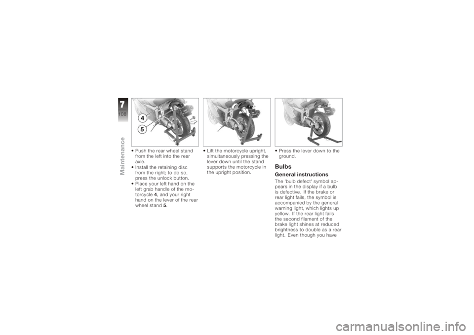
Push the rear wheel stand
from the left into the rear
axle.
Install the retaining disc
from the right; to do so,
press the unlock button.
Place your left hand on the
left grab handle of the mo-
torcycle4, and your right
hand on the lever of the rear
wheel stand 5. Lift the motorcycle upright,
simultaneously pressing the
lever down until the stand
supports the motorcycle in
the upright position.
Press the lever down to the
ground.
BulbsGeneral instructionsThe 'bulb defect' symbol ap-
pears in the display if a bulb
is defective. If the brake or
rear light fails, the symbol is
accompanied by the general
warning light, which lights up
yellow. If the rear light fails
the second filament of the
brake light shines at reduced
brightness to double as a rear
light. Even though you have
7108zMaintenance
Page 115 of 163
Turn cover1clockwise to
install.Replacing parking-light
bulb
If it is not standing firmly,
the motorcycle could
topple in the course of the
operations described below.
Always make sure that the
motorcycle is stable and
firmly supported.
Make sure the ground is
level and firm and place the
motorcycle on its stand. Switch off the ignition.
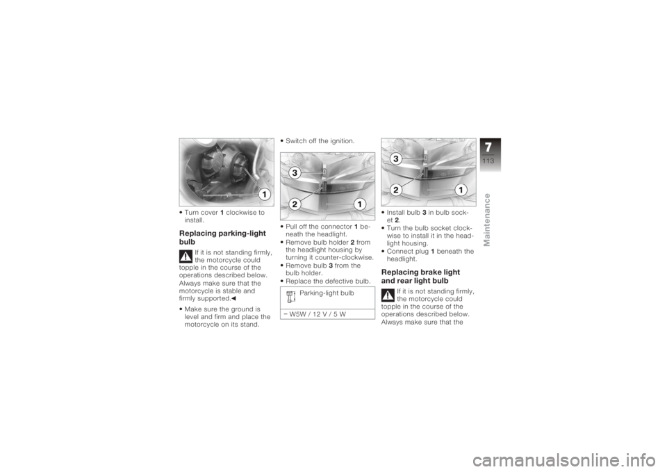
Pull off the connector
1be-
neath the headlight.
Remove bulb holder 2from
the headlight housing by
turning it counter-clockwise.
Remove bulb 3from the
bulb holder.
Replace the defective bulb.
Parking-light bulb
W5W / 12 V / 5 W Install bulb
3in bulb sock-
et 2.
Turn the bulb socket clock-
wise to install it in the head-
light housing.
Connect plug 1beneath the
headlight.
Replacing brake light
and rear light bulb
If it is not standing firmly,
the motorcycle could
topple in the course of the
operations described below.
Always make sure that the
7113zMaintenance