2006 BMW M6 COUPE rear entertainment
[x] Cancel search: rear entertainmentPage 83 of 227

Controls
81Reference
At a glance
Driving tips
Communications
Navigation
Entertainment
Mobility
5.Select "Pathway lighting" and press the
controller.
6.Turn the controller to select the desired
duration.
7.Press the controller to apply the setting.
Daytime running lamps*
If desired, the light switch can remain in posi-
tion0, 1 or 3.
In position0 and 3 the exterior lighting is auto-
matically switched off after the vehicle is
switched off. In position1 the parking lamps
light up after the ignition is switched off.
Switch on the parking lamps if required as
described under Parking lamps.
Adaptive Head Light*
The concept
Adaptive Head Light is a variable headlamp
control system that enables better illumination
of the road surface. Depending on the steering
angle and other parameters, the light from the
headlamp follows the course of the road.
Activating Adaptive Head Light
In switch position3, the Adaptive Head Light is
active and the automatic headlamp control is
switched on, refer to page80.
To avoid blinding oncoming traffic, the Adaptive
Head Light is not active when driving in reverse
and points toward the passenger side when the
vehicle is stopped.
Malfunction
The LED next to the symbol for automatic head-
lamp control flashes. The Adaptive Head Light
is malfunctioning or has failed. Have the system
checked as soon as possible.
High beams/
roadside parking lamps
1High beams
2Headlamp flasher
3Roadside parking lamps
Roadside parking lamps, left or right*
You also enjoy the option of lighting up just one
side of your vehicle when parking. When using
this function, comply with national regulations.
Switching on
After parking the vehicle, press the lever in the
desired direction3, past the resistance point.
The roadside parking lamps drain the bat-
tery. Do not leave them switched on for
long periods of time, as otherwise it may no
longer be possible to start the engine.<
Switching off
Briefly press the lever in the opposite
direction3 up to the resistance point.
High-beam assistant*
The concept
This system automatically switches the high
beams on and off again. A sensor on the front of
the interior rearview mirror controls the pro-
cess. The assistant ensures that the high
beams are switched on whenever the traffic sit-
uation allows. This reduces the strain on you
while at the same time providing you with the
best possible visibility. Of course, you can inter-
Page 95 of 227

Controls
93Reference
At a glance
Driving tips
Communications
Navigation
Entertainment
Mobility
Another storage space is located in the luggage
compartment in the right side panel. If you wish,
this is also suitable to store the onboard docu-
mentation.
Clothes hooks
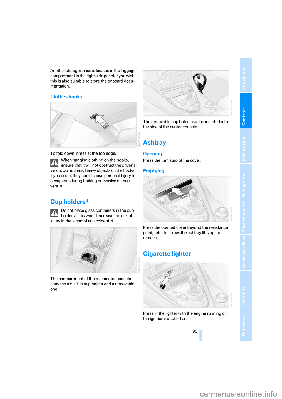
To fold down, press at the top edge.
When hanging clothing on the hooks,
ensure that it will not obstruct the driver's
vision. Do not hang heavy objects on the hooks.
If you do so, they could cause personal injury to
occupants during braking or evasive maneu-
vers.<
Cup holders*
Do not place glass containers in the cup
holders. This would increase the risk of
injury in the event of an accident.<
The compartment of the rear center console
contains a built-in cup holder and a removable
one.The removable cup holder can be inserted into
the side of the center console.
Ashtray
Opening
Press the trim strip of the cover.
Emptying
Press the opened cover beyond the resistance
point, refer to arrow: the ashtray lifts up for
removal.
Cigarette lighter
Press in the lighter with the engine running or
the ignition switched on.
Page 97 of 227

Controls
95Reference
At a glance
Driving tips
Communications
Navigation
Entertainment
Mobility
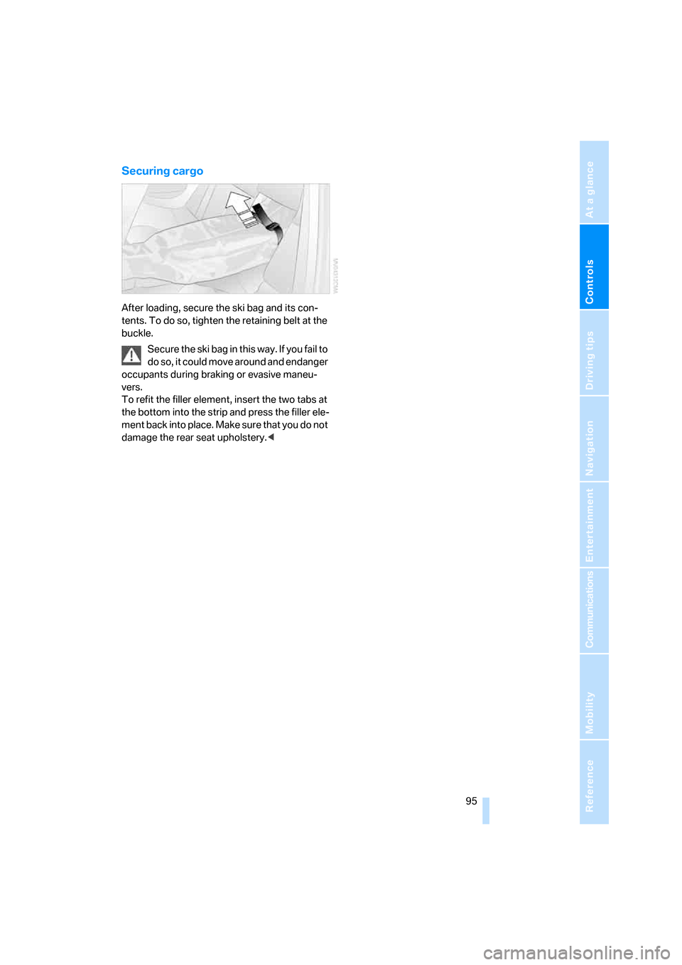
Securing cargo
After loading, secure the ski bag and its con-
tents. To do so, tighten the retaining belt at the
buckle.
Secure the ski bag in this way. If you fail to
do so, it could move around and endanger
occupants during braking or evasive maneu-
vers.
To refit the filler element, insert the two tabs at
the bottom into the strip and press the filler ele-
ment back into place. Make sure that you do not
damage the rear seat upholstery.<
Page 103 of 227

Driving tips
101Reference
At a glance
Controls
Communications
Navigation
Entertainment
Mobility
2.Determine the combined weight of the
driver and passengers that will be riding in
your vehicle.
3.Subtract the combined weight of the driver
and passengers from XXX lbs. or YYY kg.
4.The resulting figure equals the available
amount of cargo and luggage load capacity.
For example, if the XXX amount equals
800 lbs. and there will be four 150-lb. pas-
sengers in your vehicle, the amount of avail-
able cargo and luggage load capacity is
200 lbs.:
800lbs. minus 600lbs. = 200lbs.
5.Determine the combined weight of luggage
and cargo being loaded on the vehicle. That
weight may not safely exceed the available
cargo and luggage load capacity calculated
in step 4.
6.If your vehicle will be towing a trailer, part of
the load from your trailer will be transferred
to your vehicle. Consult the manual for
transporting a trailer to determine how this
may reduce the available cargo and luggage
load capacity of your vehicle.
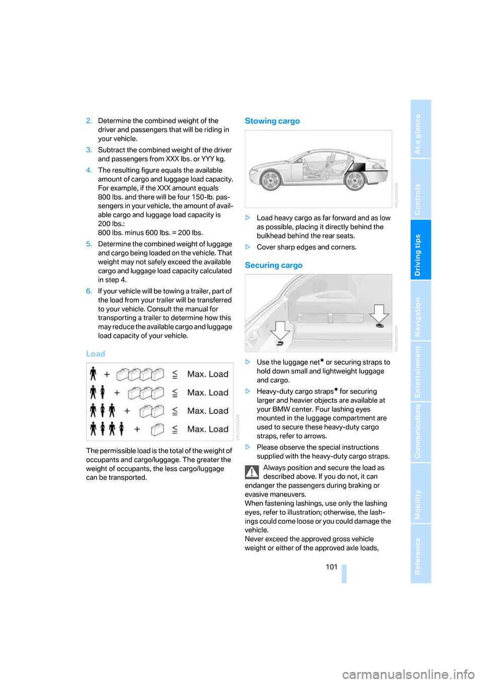
Load
The permissible load is the total of the weight of
occupants and cargo/luggage. The greater the
weight of occupants, the less cargo/luggage
can be transported.
Stowing cargo
>Load heavy cargo as far forward and as low
as possible, placing it directly behind the
bulkhead behind the rear seats.
>Cover sharp edges and corners.
Securing cargo
>Use the luggage net* or securing straps to
hold down small and lightweight luggage
and cargo.
>Heavy-duty cargo straps
* for securing
larger and heavier objects are available at
your BMW center. Four lashing eyes
mounted in the luggage compartment are
used to secure these heavy-duty cargo
straps, refer to arrows.
>Please observe the special instructions
supplied with the heavy-duty cargo straps.
Always position and secure the load as
described above. If you do not, it can
endanger the passengers during braking or
evasive maneuvers.
When fastening lashings, use only the lashing
eyes, refer to illustration; otherwise, the lash-
ings could come loose or you could damage the
vehicle.
Never exceed the approved gross vehicle
weight or either of the approved axle loads,
Page 185 of 227

Mobility
183Reference
At a glance
Controls
Driving tips
Communications
Navigation
Entertainment
procedures with correspondingly trained per-
sonnel. Due to the high voltage involved, there
is a danger to life and limb when work is carried
out improperly.<
High beams, parking lamps
The illustration shows the front left side of the
engine compartment.
High beams
Bulb 55 watts, H 7
1.Remove the cover cap1 by pressing the tab
and removing the cover cap upward.
2.Press the bulb holder from above to release
it.
3.Remove the bulb holder.
4.Remove and replace the bulb.
The lamp H7 is pressurized; wear eye
protection and protective gloves. Other-
wise there is a danger of injuries if the bulb is
accidentally damaged during replacement.<
Parking lamps
Bulb 10 watts
Bulb holder and reflector are one unit and
are replaced together.<
1.Turn the bulb holder2 to the right and
remove.
2.Press the snap connection on the plug con-
nector, pull off the bulb holder and replace.
Front turn signal, side marker
Your BMW is equipped with two turn signal
lamps per side in the front.
Turn signal lamp 1
Bulb 21 watts, WY 21 SV
The illustration shows the front right side of the
engine compartment.
1.Press the lever shown:
>downward for the right turn signal
>upward for the left turn signal
2.Remove the bulb holder towards the rear.
3.Remove and replace the bulb.
Turn signal lamp 2
Bulb 21 watts, WY 21 SV
The bulb for the turn signal lamp 2 can be
replaced via the wheel well.
The illustration shows the front left side of the
vehicle.
1.Steering turned all the way to the left or
right.
2.Turn off the light, switch off the ignition and
remove the remote control from the ignition
lock.
3.Unscrew the bolt 1 with the open-ended
wrench from the onboard toolkit, refer to
page182.
Page 187 of 227

Mobility
185Reference
At a glance
Controls
Driving tips
Communications
Navigation
Entertainment
License plate lamps
Bulb 5 watts, WY 5 W
1.Push a screwdriver from the left under the
lamp and pry out the lamp toward the right.
2.Turn the bulb holder to the left by 905 and
remove.
3.Remove and replace the bulb.
Repairing flat tire with
M Mobility System
To repair a flat tire, an M Mobility System is pro-
vided in the BMW M6. Using this system you
can apply a sealant in the inside of the tire, seal
off the damaged area, restore the tire inflation
pressure and then continue driving.
Safety measures in case of a breakdown:
park the vehicle as far as possible from
passing traffic and on solid ground. Switch on
the hazard warning flashers.
Lock the steering wheel in straight-ahead set-
ting of the wheels. Set the handbrake and
engage the first or reverse gear. Have all vehicle
occupants get out of the vehicle and ensure
that they remain outside the immediate area in a
safe place, such as behind a guardrail.
If a warning triangle or portable hazard warning
lamp is required, set it up on the roadside at an
appropriate distance from the rear of the vehi-
cle. Comply with all safety guidelines and regu-
lations.<
Preparation
The M Mobility System is located in the lug-
gage compartment under the floor panel flap.
Do not remove foreign bodies which have pen-
etrated the tire if possible.
Corresponding information on using the
M Mobility System are also provided on
the device.<
Before using the M Mobility System,
observe the information on the sealant
bottle.<
Pull the sticker for the speed limit off the sealant
bottle and apply it to the steering wheel.
Please observe the best-by date on the
sealant bottle.<
The M Mobility System consists of
1Sealant bottle and sticker with speed limit
2Filling hose from sealant bottle to wheel
Page 189 of 227

Mobility
187Reference
At a glance
Controls
Driving tips
Communications
Navigation
Entertainment
8.With the ignition switched on, refer to
page50:
Switch on the device and allow to run for
approx. 3 minutes to fill wheel with sealant.
It is not important what inflation pressure
the tire has after filling.
9.Switch off device.
10.Remove connecting hose from connection
of sealant bottle and tire valve.
Stow the M Mobility System in the vehicle
again.
Distributing sealant
Immediately drive approx. 2 miles/3 km so that
sealant is evenly distributed in tire.
Do not exceed a maximum speed of
35 mph/60 km/h. Do not drop below
12 mph/20 km/h if possible.<
Producing tire inflation pressure
1.After approx. 2 miles/3 km, stop at suitable
location.
2.Screw compressor hose9 directly onto tire
valve.
3.Insert connector 3 in lighter socket in vehi-
cle interior.
4.Correct tire inflation pressure to 29 psi/
200 kPa. With the ignition switched on:
>Increase inflation pressure: switch on
device, position I. To check currently set
inflation pressure, briefly switch off
device.
Do not allow compressor to run
longer than 10 minutes, otherwise
the device will overheat and may be dam-
aged.<
>Reduce inflation pressure: press but-
ton8 or turn screw8 on pressure gauge.
If the inflation pressure is not held, drive
the vehicle again, refer to Distributing
sealant. Then repeat steps 1 to 4 once.
Using the M Mobility System can be ineffective
with tire damage from a size of approx. 0.16 in/
4 mm. Please contact the nearest BMW center,
refer to page192, or a workshop that works according to BMW repair procedures with cor-
respondingly trained personnel if the tire can-
not be made ready for driving with the
M Mobility System.<
The tire inflation pressure must be at least
29 psi/200 kPa. Otherwise do not con-
tinue driving.<
Continue driving
Do not exceed the permissible maximum
speed of 50 mph/80 km/h, otherwise
accidents can occur.<
Reinitialize the Flat Tire Monitor.
For details, refer to page74.
Have the defective tire and the sealant bottle of
the M Mobility System replaced as soon as
possible.<
Changing wheels
Safety precautions in the event of a flat
tire or wheel change: park the vehicle as
far as possible from passing traffic and on solid
ground. Switch on the hazard warning flashers.
Lock the steering wheel in straight-ahead set-
ting of the wheels. Set the handbrake and
engage a driving position with the selector
lever.
Have all vehicle occupants get out of the vehicle
and ensure that they remain outside the imme-
diate area in a safe place, such as behind a
guardrail.
If a warning triangle or portable hazard warning
lamp is required, set it up on the roadside at an
appropriate distance from the rear of the vehi-
cle. Comply with all safety guidelines and regu-
lations.
Change the wheel only on a level, firm surface
which is not slippery. The vehicle or the jack
could slip to the side if you attempt to raise the
vehicle on a soft or slippery surface such as
snow, ice, tiles, etc.
Position the jack on a firm support surface.
Do not use a wooden block or similar object as a
support base for the jack, as this would prevent
it from extending to its full support height and
reduce its load-carrying capacity.
Page 195 of 227

Mobility
193Reference
At a glance
Controls
Driving tips
Communications
Navigation
Entertainment
1.Fold open the cover of the BMW jump-
starting terminal. To do so, pull the tab.
2.Attach one end of the jumper cable plus/+
to the positive terminal of the battery or a
starting-aid terminal of the vehicle provid-
ing assistance.
3.Attach the second end of the cable to the
positive terminal of the battery or to a jump-
starting terminal of the vehicle to be started.
4.Attach one end of the jumper cable minus/–
to the negative terminal of the battery or to
an engine or body ground of the vehicle
providing assistance.
Your BMW M6 has a special nut as body
ground or negative terminal.
5.Attach the second end of the cable to the
negative terminal of the battery or to the
engine or body ground of the vehicle to be
started.
Starting engine
1.Start the engine on the assisting vehicle
and allow it to run at idle for several minutes
at slightly increased speed.
2.Start the engine on the other vehicle in the
usual way.
If the first starting attempt is not successful, wait a few minutes before another attempt
in order to allow the discharged battery to
recharge.
3.Let the engines run for a few minutes.
4.Disconnect the jumper cables by reversing
the connection sequence.
Check the battery and recharge if necessary.
Never use spray fluids to start the
engine.<
Tow-starting and towing
Observe applicable laws and regulations
for tow-starting and towing.<
Do not transport any passengers other
than the driver in a vehicle that is being
towed.<
Using tow fitting
The threaded tow fitting is stored in the tool kit
mounted on the inside of the luggage compart-
ment under the floor mat, refer to page182, and
should always remain in the vehicle. It can be
screwed in at the front or rear of the BMW M6.
Only use the tow fitting that comes with
the vehicle and screw it in as far as possi-
ble. Use the tow fitting for towing only on roads.
Avoid lateral loading of the tow fitting, e.g. do
not lift the vehicle by the tow fitting. Otherwise,
the tow fitting and vehicle can be damaged.<
Access to screw thread
Round cover in bumper:
Press the arrow symbol on the cover.
Front