2006 BMW 325CI service
[x] Cancel search: servicePage 20 of 174

20
Dynamic Brake Control (DBC)
●
Malfunction in the DBC system.
Conventional braking efficiency
is available and unrestricted.
Have the system checked as soon as
possible.
For additional information, refer to
page 115.
Dynamic Brake Control (DBC)
warning lamp for Canadian
models.
Add washer fluid
The washer fluid level is too low,
top it up at the earliest opportu-
nity.
For additional information, refer to
page 126.
CHECK GAS CAP*
●
This indicator lamp comes on
when the gas cap is loose or
missing.
Close the gas cap tightly: refer to
page 24.
SERVICE ENGINE SOON
●
If the indicator lamp comes on
either continuously or intermit-
tently, this indicates a fault in the emis-
sions-related electronic systems.
Although the vehicle remains opera-
tional, you should have the systems
checked by your BMW center at the
earliest possible opportunity.
For additional information, refer to
page 132.
Service Engine Soon indicator
lamp for Canadian models.
Engine electronics
●
There is a fault in the electronic
engine-management system.
You can continue to drive with reduced
engine output or engine speed. Please
have the system inspected at your
BMW center.
Add coolant
The coolant level is too low. Add
coolant at the earliest opportu-
nity.
For additional information, refer to
page 128.
Green: for your information
Turn signal indicator
Flashes when the turn signal is
operated.
Rapid flashing indicates a system mal-
function.
For additional information, refer to
page 70.
Cruise control
Lights up when the cruise con-
trol is activated. Ready for oper-
ation via the buttons in the steering
wheel.
For additional information, refer to
page 72.
Front fog lamps
Lights up whenever you switch
on the front fog lamps.
For additional information, refer to
page 87.
Blue: for your information
High beams
Comes on when the high beams
are on or the headlamp flasher
is actuated.
For additional information, refer to
pages 70, 87.
Indicator and warning lamps
Page 22 of 174

22
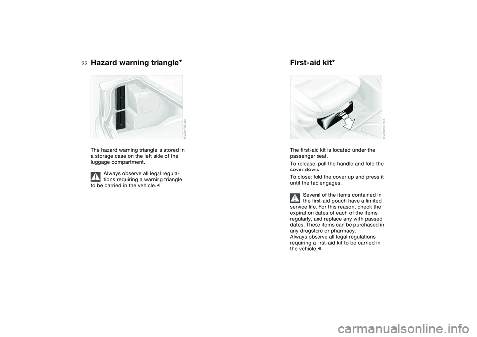
Hazard warning triangle*
The hazard warning triangle is stored in
a storage case on the left side of the
luggage compartment.
Always observe all legal regula-
tions requiring a warning triangle
to be carried in the vehicle.
<
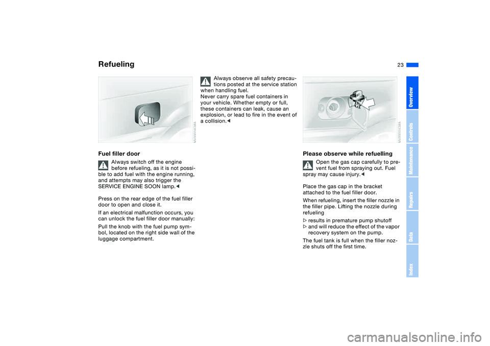
First-aid kit*The first-aid kit is located under the
passenger seat.
To release: pull the handle and fold the
cover down.
To close: fold the cover up and press it
until the tab engages.
Several of the items contained in
the first-aid pouch have a limited
service life. For this reason, check the
expiration dates of each of the items
regularly, and replace any with passed
dates. These items can be purchased in
any drugstore or pharmacy.
Always observe all legal regulations
requiring a first-aid kit to be carried in
the vehicle.<
Page 23 of 174

23
RefuelingFuel filler door
Always switch off the engine
before refueling, as it is not possi-
ble to add fuel with the engine running,
and attempts may also trigger the
SERVICE ENGINE SOON lamp.<
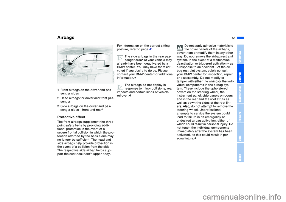
Press on the rear edge of the fuel filler
door to open and close it.
If an electrical malfunction occurs, you
can unlock the fuel filler door manually:
Pull the knob with the fuel pump sym-
bol, located on the right side wall of the
luggage compartment.
Always observe all safety precau-
tions posted at the service station
when handling fuel.
Never carry spare fuel containers in
your vehicle. Whether empty or full,
these containers can leak, cause an
explosion, or lead to fire in the event of
a collision.<
Please observe while refuelling
Open the gas cap carefully to pre-
vent fuel from spraying out. Fuel
spray may cause injury.<
Place the gas cap in the bracket
attached to the fuel filler door.
When refueling, insert the filler nozzle in
the filler pipe. Lifting the nozzle during
refueling
>results in premature pump shutoff
>and will reduce the effect of the vapor
recovery system on the pump.
The fuel tank is full when the filler noz-
zle shuts off the first time.
OverviewControlsMaintenanceRepairsDataIndex
Page 27 of 174

27
Overview
Controls and features
Operation, maintenance
Owner service procedures
Technical data
Index
OverviewControlsMaintenanceRepairsDataIndex
Page 51 of 174

51 Passenger safety systems
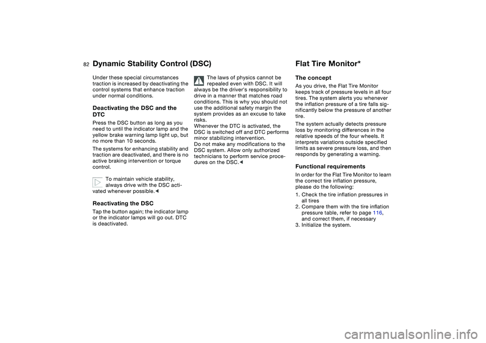
Airbags1Front airbags on the driver and pas-
senger sides
2Head airbags for driver and front pas-
senger
3Side airbags on the driver and pas-
senger sides – front and rear*Protective effectThe front airbags supplement the three-
point safety belts by providing addi-
tional protection in the event of a
severe frontal collision in which the pro-
tection afforded by the belts alone may
no longer be sufficient. The head and
side airbags help provide protection in
the event of a collision from the side.
The respective side airbag helps sup-
port the seat occupant's upper body.
For information on the correct sitting
posture, refer to page 41.
The side airbags in the rear pas-
senger area* of your vehicle may
already have been deactivated by a
BMW center. You may have them acti-
vated if you desire to do so. Please
contact your BMW center for additional
information.<
The airbags do not deploy in
response to minor collisions, rear
impacts and certain kinds of vehicle
rollover.<
Do not apply adhesive materials to
the cover panels of the airbags,
cover them or modify them in any other
way. Do not remove the airbag restraint
system. In the event of a malfunction,
deactivation or triggered activation – as
a response to an accident – of the air-
bag restraint system, solely consult
your BMW center for inspection, repair
or disassembly. Do not modify or
tamper with either the wiring or the indi-
vidual components in the airbag sys-
tem. These include the upholstered
covers on the steering wheel, the
instrument panel, side panels on doors
and in the rear and the roof struts as
well as down the sides of the roof lin-
ers. Also, do not attempt to remove the
steering wheel. Unprofessional
attempts to service the system could
lead to failure in an emergency or
undesired airbag activation, either of
which could result in personal injury. Do
not touch the individual components
immediately after the system has been
activated, as this could result in per-
sonal injury.<
OverviewControlsMaintenanceRepairsDataIndex
Page 60 of 174

60
If the engine does not start on the first
attempt – if it is very hot or cold, for
instance:
>Press the accelerator pedal halfway
down while engaging the starter.
Cold starts at extremely low tempera-
tures below +57/–156 and at alti-
tudes of over approx. 3,300 ft/1,000 m:
>On the first start attempt, it may be
necessary to engage the starter for a
longer period, but no longer than
20 seconds
>Press the accelerator pedal halfway
down while engaging the starter.
Extended starting attempts, char-
acterized by excessively frequent
or long periods with the starter
engaged can damage the catalytic con-
verter.<
Engine idle speed is controlled by the
engine computer system. Increased
speeds at start-up are normal and
should decrease as the engine warms
up. If engine speed does not decrease,
service is required.
To prevent the battery from discharg-
ing, always deactivate electrical
devices that are not in use. Switch the
ignition off when the vehicle is not
being driven.Manual transmission1. Engage the parking brake
2. Gearshift lever in idling position
3. Depress the clutch pedal.
If the clutch pedal is not depressed,
the engine cannot be started
4. Start the engine.Automatic transmission1. Depress footbrake
2. Place the selector lever in position P
or N
3. Start the engine.
To prevent the vehicle from start-
ing off on its own, always move
the selector lever to position P and
engage the parking brake before leav-
ing your vehicle with the engine run-
ning.
Do not leave the vehicle unattended
with the engine running. An unattended
vehicle with a running engine repre-
sents a safety hazard.<
Sequential manual gearbox SMG1. Depress footbrake
2. Move selector lever into position N
3. Start the engine.
If the engine does not start, reen-
gage the gear last selected, refer
to the gear indicator in the display, and
move the selector lever into neutral
position N again.
The gearbox is automatically taken out
of gear if the driver's door is opened
while the engine is running and the
driver does not actuate the pedals, the
shift paddles or the selector lever. This
is accompanied by a warning tone and
the flashing gear indicator. The gear
display N appears in the instrument
cluster.<
Before exiting the vehicle with the
engine running, move the selector
lever into position N and apply the park-
ing brake.
Do not leave the vehicle unattended
with the engine running. An unattended
vehicle with a running engine repre-
sents a safety hazard.<
Starting the engine
Page 76 of 174

76
Service interval displayRemaining distance to next
serviceThe displays shown in the illustration
appear for a few seconds when the
ignition key is in position 1 or higher or
after the engine is started.
The next service due appears with the
message OIL SERVICE or
INSPECTION, together with the dis-
tance remaining in miles – in kilometers
in Canada – before the next scheduled
service.
The computer bases its calculations of
the remaining distance on the preced-
ing driving style.
A flashing message and a "–" in front of
the number mean that the service inter-
val has already been exceeded by the
distance shown on the display. Please
contact your BMW center for an
appointment.
Check ControlWhen the ignition key is in position 2,
the following information and/or condi-
tions are indicated using symbols until
the conditions have been corrected.
1Check the low beams and high
beams, as well as the parking lamps
2Door open
3Luggage compartment lid open
4Check tail or brake lamps
When you open the driver's door after
having turned the ignition key to posi-
tion 0, you will hear an acoustic signal
for a few seconds to remind you that
the lamps have not been switched off.
Page 82 of 174

82
Under these special circumstances
traction is increased by deactivating the
control systems that enhance traction
under normal conditions.Deactivating the DSC and the
DTCPress the DSC button as long as you
need to until the indicator lamp and the
yellow brake warning lamp light up, but
no more than 10 seconds.
The systems for enhancing stability and
traction are deactivated, and there is no
active braking intervention or torque
control.
To maintain vehicle stability,
always drive with the DSC acti-
vated whenever possible.
is deactivated.
The laws of physics cannot be
repealed even with DSC. It will
always be the driver's responsibility to
drive in a manner that matches road
conditions. This is why you should not
use the additional safety margin the
system provides as an excuse to take
risks.
Whenever the DTC is activated, the
DSC is switched off and DTC performs
minor stabilizing intervention.
Do not make any modifications to the
DSC system. Allow only authorized
technicians to perform service proce-
dures on the DSC.<
Flat Tire Monitor*The conceptAs you drive, the Flat Tire Monitor
keeps track of pressure levels in all four
tires. The system alerts you whenever
the inflation pressure of a tire falls sig-
nificantly below the pressure of another
tire.
The system actually detects pressure
loss by monitoring differences in the
relative speeds of the four wheels. It
interprets variations outside specified
limits as severe pressure loss, and then
responds by generating a warning.Functional requirementsIn order for the Flat Tire Monitor to learn
the correct tire inflation pressure,
please do the following:
1. Check the tire inflation pressures in
all tires
2. Compare them with the tire inflation
pressure table, refer to page 116,
and correct them, if necessary
3. Initialize the system.
Dynamic Stability Control (DSC)