2006 Alfa Romeo Brera/Spider tow
[x] Cancel search: towPage 25 of 267

23
SAFETY
DEVICES
WARNING
LIGHTS AND
MESSAGES
IN AN
EMERGENCY
CAR
MAINTENANCE
TECHNICAL
SPECIFICATIONS
INDEX
DASHBOARD
AND
CONTROLS
CORRECT USE
OF THE CAR
IMPORTANTUnder certain conditions
(heavy slopes, for instance), the reading
on the gauge may differ from the actual
amount of fuel in the tank and changes
in level may be indicated late. This con-
dition falls within the regular operating log-
ics of the fuel gauge.The turning on of the warning light u
(together with a message on the dis-
play) indicates that the coolant fluid
temperature is too high; in this case,
stop the engine and contact Alfa Romeo
Authorized Services.
IMPORTANTThe temperature of the
engine coolant may rise towards the
maximum values (red sector) when the
car is driven at low speeds, uphill, fully
laden or during towing, especially if the
ambient temperature is high.
A0F0178mfig. 16
ENGINE COOLANT
TEMPERATURE GAUGE
fig. 16
This shows the temperature of the en-
gine coolant fluid and begins working
when the fluid temperature exceeds ap-
prox. 50°C.
The pointer should normally be towards
the middle of the scale. If the pointer
reaches the red sector, reduce your de-
mand on the engine.
Page 26 of 267

24
SAFETY
DEVICES
WARNING
LIGHTS AND
MESSAGES
IN AN
EMERGENCY
CAR
MAINTENANCE
TECHNICAL
SPECIFICATIONS
INDEX
DASHBOARD
AND
CONTROLS
CORRECT USE
OF THE CARENGINE OIL TEMPERATURE
GAUGE
(petrol versions) fig. 17
This shows the temperature of the en-
gine oil and begins working when the
oil temperature exceeds approx. 70°C.
If the pointer reaches the red sector, re-
duce your demand on the engine.
A0F0179mfig. 17
The turning on of the warning light `
when travelling (together with a mes-
sage on the display) indicates that the
oil temperature is too high; in this case,
stop the engine and contact Alfa Romeo
Authorized Services.
IMPORTANTThe temperature of the
engine oil may rise towards the maxi-
mum values (red sector) when the car
is driven at low speeds, uphill, fully
laden or during towing, especially if the
ambient temperature is high.
A0F0180mfig. 18
TURBOCHARGER PRESSURE
GAUGE (diesel versions)
fig. 18
This shows the turbocharger pressure
value.
Page 53 of 267

51
SAFETY
DEVICES
WARNING
LIGHTS AND
MESSAGES
IN AN
EMERGENCY
CAR
MAINTENANCE
TECHNICAL
SPECIFICATIONS
INDEX
DASHBOARD
AND
CONTROLS
CORRECT USE
OF THE CAR
AIR DISTRIBUTION
SELECTION
O: air flow to driver’s/passenger’s
body;
M: air flow to driver’s/passenger’s
body and lower part of the passenger
compartment;
N: air flow towards the front and rear
lower part of the passenger compart-
ment;
Q: air flow towards the lower part of
the passenger compartment and wind-
screen;
ü: air flow towards the windscreen
MANUAL CLIMATE
CONTROL SYSTEM
(where provided)
CONTROLS fig. 41
A- Air temperature knob (mixing warm
and cold air);
B- Air distribution knob;
C- Fan speed knob;
D- Heated rear window and door mir-
ror defrosting on/off button;
E- Windscreen, front side windows and
door mirror max. demisting/defrosting
on/off button;
F- Air recirculation on/off button;
G- Compressor on/off button.
fig. 41A0F0011m
Page 63 of 267

61
SAFETY
DEVICES
WARNING
LIGHTS AND
MESSAGES
IN AN
EMERGENCY
CAR
MAINTENANCE
TECHNICAL
SPECIFICATIONS
INDEX
DASHBOARD
AND
CONTROLS
CORRECT USE
OF THE CAR
AIR DISTRIBUTION
SELECTION
Pressing buttons N/O/˙you can
manually choose one of the 7 possible
modes for air distribution inside the com-
partment:
˙Flow of air to the dashboard centre
and side outlets (passenger’s body).
O˙Splitting of the air flow between
the vents to the lower part of the
passenger compartment (warmest
air) and the dashboard centre and
side outlets (coolest air).
OAir flow towards the lower part of the
passenger compartment. This type
of distribution allows heating of the
passenger compartment in the short-
est time.
NSplitting of the air flow between
Owindscreen and front side window
demisting/defrosting vents and the
lower part of the passenger com-
partment. This type of air distribu-
tion allows satisfactory heating of
the passenger compartment while
preventing possible misting of the
windows.
NAir flow to the windscreen and front
side window vents to demist or de-
frost them.
N˙Splitting of the air flow between
the central/side dashboard vents
and windscreen and side window
defrosting/demisting vents. This
type of air distribution allows satis-
factory ventilation of the passenger
compartment while preventing pos-
sible misting of the windows.
N˙Splitting of the air flow between
all vents.
O
To restore automatic air distribution con-
trol after a manual selection, press but-
ton AUTO. Temperature detection (compressor off
and outside temperature higher than set
temperature) is activated each time the
electronic key is fitted into the ignition
device.
Operation of the cli-
mate control compres-
sor is necessary for cooling
and dehumidifying the air; it is
advisable to keep this function
always on, to prevent window
misting problems.
WARNING
Page 67 of 267

65
SAFETY
DEVICES
WARNING
LIGHTS AND
MESSAGES
IN AN
EMERGENCY
CAR
MAINTENANCE
TECHNICAL
SPECIFICATIONS
INDEX
DASHBOARD
AND
CONTROLS
CORRECT USE
OF THE CAR
EXTERNAL LIGHTS
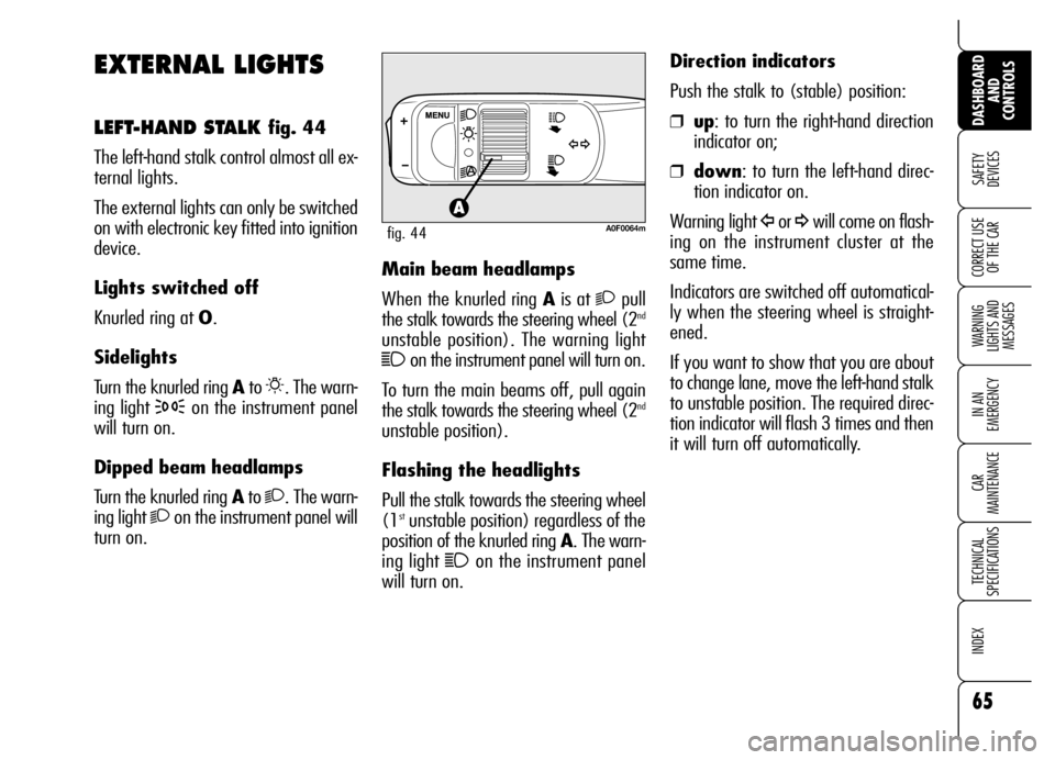
LEFT-HAND STALK fig. 44
The left-hand stalk control almost all ex-
ternal lights.
The external lights can only be switched
on with electronic key fitted into ignition
device.
Lights switched off
Knurled ring at O.
Sidelights
Turn the knurled ring Ato
6. The warn-
ing light
3on the instrument panel
will turn on.
Dipped beam headlamps
Turn the knurled ring Ato
2. The warn-
ing light
2on the instrument panel will
turn on.Main beam headlamps
When the knurled ring Ais at
2pull
the stalk towards the steering wheel (2nd
unstable position). The warning light
1on the instrument panel will turn on.
To turn the main beams off, pull again
the stalk towards the steering wheel (2
nd
unstable position).
Flashing the headlights
Pull the stalk towards the steering wheel
(1
stunstable position) regardless of the
position of the knurled ring A. The warn-
ing light
1on the instrument panel
will turn on.Direction indicators
Push the stalk to (stable) position:
❒up: to turn the right-hand direction
indicator on;
❒down: to turn the left-hand direc-
tion indicator on.
Warning light
Îor ¥will come on flash-
ing on the instrument cluster at the
same time.
Indicators are switched off automatical-
ly when the steering wheel is straight-
ened.
If you want to show that you are about
to change lane, move the left-hand stalk
to unstable position. The required direc-
tion indicator will flash 3 times and then
it will turn off automatically.A0F0064mfig. 44
Page 68 of 267

66
SAFETY
DEVICES
WARNING
LIGHTS AND
MESSAGES
IN AN
EMERGENCY
CAR
MAINTENANCE
TECHNICAL
SPECIFICATIONS
INDEX
DASHBOARD
AND
CONTROLS
CORRECT USE
OF THE CAR
“FOLLOW ME HOME”
DEVICE
This function allows the illumination of
the space in front of the car for a pre-
set period of time.
Activation
Pull the stalk towards the steering wheel
within 2 minutes from when the engine
is turned off.
At each single movement of the stalk,
the staying on of the lights is extended
by 30 seconds up to a maximum of 3.5
minutes; then the lights are switched off
automatically.
Each time the stalk is operated, the
3
warning light turns on together with the
message on the display (see section
“Warning lights and messages”).
Deactivation
Keep the stalk pulled towards the steer-
ing wheel for more than 2 seconds.
AUTOMATIC HEADLIGHTS
SENSOR (daylight sensor)
(where provided)
It detects the changes of the external
light intensity of the car according to the
light sensitivity set: the greater the sen-
sitivity is, the smaller the amount of ex-
ternal light necessary to control the
switching-on of the external headlights
will be.
The daylight sensor sensitivity can be ad-
justed through the “Setup Menu” of the
display (see “Reconfigurable multifunc-
tion display” in this section).
Activation
Turn the knurled ring A-fig. 44to
2A:
in this way, the automatic activation of
the side/taillights and dipped beam
headlights is simultaneously enabled ac-
cording to outside brightness.
With lights switched on automatically
and in the presence of a switching off
control by the sensor, the main beams
will be switched off first and a few sec-
onds after also the sidelights.Deactivation
As a result of the sensor control, the
dipped beam headlights will switch off
and, after a few seconds, sidelights will
switch off too. The sensor is not able
to detect the fog presence, lights shall
therefore be switched on manually.
Failure warnings
Headlight sensor failure is shown by a
dedicated message on the display (see
section “Warning lights and mes-
sages”).
Page 71 of 267

69
SAFETY
DEVICES
WARNING
LIGHTS AND
MESSAGES
IN AN
EMERGENCY
CAR
MAINTENANCE
TECHNICAL
SPECIFICATIONS
INDEX
DASHBOARD
AND
CONTROLS
CORRECT USE
OF THE CAR
The rain sensor is activated automatical-
ly moving the right-hand stalk to position
1-fig. 47and it has a range of adjust-
ment that gradually varies between wiper
stationary (no wiping) when the wind-
screen is dry, to wiper at second speed
(continuous, medium) with heavy rain.
Turning the knurled ringA-fig. 47it
is possible to increase the sensitivity of
the rain sensor, obtaining a quicker
change from stationary (no wiping)
when the windscreen is dry, to first con-
tinuous speed (continuous, slow). This
action is confirmed by one wiping
stroke.
Operating the windscreen washer with
the rain sensor activated (stalk at posi-
tion 1-fig. 47) the normal washing
cycle is performed at the end of which
the rain sensor resumes its normal au-
tomatic function. “Smart washing” function
Pulling the stalk towards the steering
wheel (unstable position) operates the
windscreen washer.
Keeping the stalk pulled with just one
movement it is possible to operate the
washer jet and the wiper at the same
time; the wiper actually comes into op-
eration automatically when the stalk is
pulled for more than half a second.
The wiper stops working 3 strokes after
releasing the stalk; a further stroke af-
ter about 6 seconds will complete the
wiping operation.
RAIN SENSOR
(where provided)
The rain sensor A-fig. 48, located be-
hind the driving mirror, is an electronic de-
vice combined with the windscreen wiper
which has the purpose of automatically
adjusting the number of wipes during in-
termittent operation, to intensity of the
rain. All the other functions controlled by
the right-hand stalk remain unchanged.
A0F0227mfig. 48
Page 73 of 267

71
SAFETY
DEVICES
WARNING
LIGHTS AND
MESSAGES
IN AN
EMERGENCY
CAR
MAINTENANCE
TECHNICAL
SPECIFICATIONS
INDEX
DASHBOARD
AND
CONTROLS
CORRECT USE
OF THE CARHEADLIGHT WASHERS
(where provided) fig. 49
Headlight washers are visible and are fit-
ted with a nozzle for each external light
function. They come into operation au-
tomatically when operating the wind-
screen washer with external lights
turned on.
IMPORTANT Check at regular inter-
vals correct operation and cleanness of
nozzles.
Make sure the device is
off when cleaning the
windscreen.
WARNING
A0F0046mfig. 49
Streaks of water could
cause non-required blade
movements.Rear window washer/wiper
Pulling the stalk towards the steering
wheel (unstable position) operates the
rear window washer and wiper. Release
the stalk to stop operation.
Turning the knurled ring B-fig. 47from
ON/OFFto
&obtains rear window
wiper intermittent operation.