Page 95 of 267

93
SAFETY
DEVICES
WARNING
LIGHTS AND
MESSAGES
IN AN
EMERGENCY
CAR
MAINTENANCE
TECHNICAL
SPECIFICATIONS
INDEX
DASHBOARD
AND
CONTROLS
CORRECT USE
OF THE CAR
TAILGATE CLOSING
Lower the tailgate pressing the lock un-
til hearing the locking click.
IMPORTANT Before closing the boot,
check whether you have with you the
ignition key since the tailgate will be
locked automatically.
The addition of objects
(speakers, spoilers, etc.)
on the rear shelf or boot
lid, except those envisaged by
the manufacturer, may prevent
the gas filled struts at the sides
of the boot from working prop-
erly.
When using the boot,
make sure the loads do
not exceed the permitted
weight (see “Technical specifi-
cations” chapter). Also make
sure the items in the boot are
arranged properly to prevent
them being thrown forwards
and injuring passengers should
you brake sharply.
WARNING
Never travel with ob-
jects on the rear shelf
to prevent them being thrown
forwards and injuring passen-
gers in case of accident or
sharp braking.
WARNING
EXTENDING THE BOOT
The double rear seat enables to extend
the boot totally or partially by splitting
one of the two seat section, thus ob-
taining different loading spaces accord-
ing to the number of rear passengers.
When driving at night
with heavy loads in the
boot, check and adjust, if re-
quired, the low beams
height (see paragraph “Head-
lights” in this section).
WARNING
Page 96 of 267

❒raise backrest retaining levers A-
fig. 76and tilt the backrests for-
ward in order to obtain a single load-
ing surface fig. 77(when raising
lever Athe “red band” Bwill ap-
pear).
Partial extension
Proceed as follows:
❒move seat belt aside; check that the
seat belt is not twisted;
❒lower completely the rear seat head
restraint;
❒raise backrest retaining lever A-fig.
76and tilt the backrest forward
(when raising lever Athe “red
band” Bwill appear). Removing the rear parcel
shelf
Proceed as follows:
❒release both rod ends A-fig. 74
supporting the rear parcel shelf Bby
removing the eyelets Cfrom pins D;
❒release the pins E-fig. 75set out-
side the shelf from their seats Fon
side supports, then remove the rear
parcel shelf.Total extension
Proceed as follows:
❒move seat belts aside; check that the
seat belt is not twisted;
❒lower completely the rear seat head
restraints;
94
SAFETY
DEVICES
WARNING
LIGHTS AND
MESSAGES
IN AN
EMERGENCY
CAR
MAINTENANCE
TECHNICAL
SPECIFICATIONS
INDEX
DASHBOARD
AND
CONTROLS
CORRECT USE
OF THE CAR
A0F0243mfig. 74A0F0244mfig. 75
A0F0085mfig. 76
A0F0253mfig. 77
Page 97 of 267

95
SAFETY
DEVICES
WARNING
LIGHTS AND
MESSAGES
IN AN
EMERGENCY
CAR
MAINTENANCE
TECHNICAL
SPECIFICATIONS
INDEX
DASHBOARD
AND
CONTROLS
CORRECT USE
OF THE CAR
To return the rear seat
back to its original position
Move aside the seat belts, check that
they are not twisted.
Raise the seat backrests and push them
back until hearing the locking click of
both retainers; the “red band” Baside
the levers Ashall no longer be visible.
The “red band” Bactually indicates that
the backrest is not properly secured.
Make sure the backrest
is properly secured at
both sides (“red bands” B-fig.
76 not visible) to prevent it
moves forward in the event of
sharp braking causing injuries
to passengers.
WARNING
ANCHORING THE LOAD
The boot houses 4 hooks for anchoring
ropes in order to guarantee perfect load
anchoring.
On certain versions, hooks B-fig. 78
can be located on the boot sides.
A0F0131mfig. 78
A heavy load that has
not been secured may
cause serious harm.
WARNING
If you want to carry
reserve fuel in a can,
follow law regulations, only
using a certified can, suitably
fastened to the load securing
eyelets. Even in this way the
risk of fire is increased in the
case of an accident.
WARNING
Page 98 of 267
96
SAFETY
DEVICES
WARNING
LIGHTS AND
MESSAGES
IN AN
EMERGENCY
CAR
MAINTENANCE
TECHNICAL
SPECIFICATIONS
INDEX
DASHBOARD
AND
CONTROLS
CORRECT USE
OF THE CAR
BONNET
TO OPEN THE BONNET
Proceed as follows:
❒pull lever A-fig. 81until hearing
the releasing click;
❒keep the lever B-fig. 82 pulled
and raise the bonnet
IMPORTANT Bonnet raising is aid-
ed by two gas springs. Do not tamper
with these springs and guide the bonnet
while raising it.
LUGGAGE COVER
(where provided)
The luggage cover shall be used to
arrange luggage and/or to carry light
objects.
The cover shall be secured to the two
hooks (one per side) A-fig. 79locat-
ed in the boot.
A0F00010mfig. 79
CARGO BOX
(where provided)
It is a special box fig. 80, to be used
to house objects in the boot, that en-
ables to obtain a level loading surface.
A0F0007mfig. 80
Page 99 of 267

97
SAFETY
DEVICES
WARNING
LIGHTS AND
MESSAGES
IN AN
EMERGENCY
CAR
MAINTENANCE
TECHNICAL
SPECIFICATIONS
INDEX
DASHBOARD
AND
CONTROLS
CORRECT USE
OF THE CAR
IMPORTANTAlways check that the
bonnet is closed properly to avoid its
opening while the car is travelling.
A0F0122mfig. 81
A0F0158mfig. 82
TO CLOSE THE BONNET
Lower the bonnet at approx. 20 cen-
timetres from the engine compartment
and then let it drop, ensuring that it is
fully closed and not just held in position
by the safety catch. If the bonnet does
not close properly, do not push it down
but open it again and repeat the above
procedure.
Improper bonnet closing is indicated by
symbol
Sand a message on the dis-
play (see section “Warning lights and
messages”).
Carry out operations
only when the car is
stationary.
WARNING
For safety reasons the
bonnet must be closed
properly to avoid its opening
while the car is travelling.
Therefore, always check it is
properly closed and the catch
engaged. Should you notice
that the catch is not perfectly
engaged when travelling, stop
the car immediately and close
the bonnet.
WARNING
IMPORTANT Before opening the bon-
net, check that windscreen wiper arms
are not lifted from the windscreen or the
wiper is working.
Page 100 of 267

98
SAFETY
DEVICES
WARNING
LIGHTS AND
MESSAGES
IN AN
EMERGENCY
CAR
MAINTENANCE
TECHNICAL
SPECIFICATIONS
INDEX
DASHBOARD
AND
CONTROLS
CORRECT USE
OF THE CAR
ROOF RACK/
SKI RACK
Certain versions can be preset for in-
stalling suitable roof racks/ski racks.
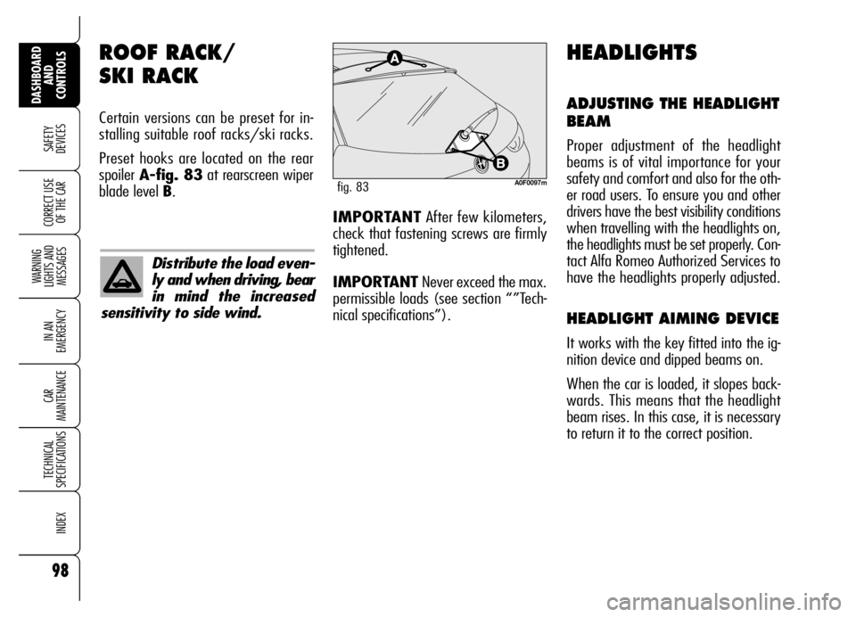
Preset hooks are located on the rear
spoiler A-fig. 83at rearscreen wiper
blade level B.
A0F0097mfig. 83
HEADLIGHTS
ADJUSTING THE HEADLIGHT
BEAM
Proper adjustment of the headlight
beams is of vital importance for your
safety and comfort and also for the oth-
er road users. To ensure you and other
drivers have the best visibility conditions
when travelling with the headlights on,
the headlights must be set properly. Con-
tact Alfa Romeo Authorized Services to
have the headlights properly adjusted.
HEADLIGHT AIMING DEVICE
It works with the key fitted into the ig-
nition device and dipped beams on.
When the car is loaded, it slopes back-
wards. This means that the headlight
beam rises. In this case, it is necessary
to return it to the correct position.
Distribute the load even-
ly and when driving, bear
in mind the increased
sensitivity to side wind.
IMPORTANTAfter few kilometers,
check that fastening screws are firmly
tightened.
IMPORTANTNever exceed the max.
permissible loads (see section “”Tech-
nical specifications”).
Page 101 of 267

99
SAFETY
DEVICES
WARNING
LIGHTS AND
MESSAGES
IN AN
EMERGENCY
CAR
MAINTENANCE
TECHNICAL
SPECIFICATIONS
INDEX
DASHBOARD
AND
CONTROLS
CORRECT USE
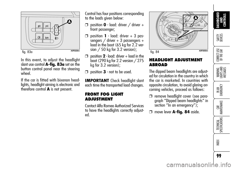
OF THE CARIn this event, to adjust the headlight
slant use control A-fig. 83aset on the
button control panel near the steering
wheel.
If the car is fitted with bixenon head-
lights, headlight aiming is electronic and
therefore control Ais not present.Control has four positions corresponding
to the loads given below:
❒position 0- load: driver / driver +
front passenger;
❒position 1- load: driver + 3 pas-
sengers / driver + 3 passengers +
load in the boot (65 kg for 2.2 ver-
sion / 50 kg for 3.2 version);
❒position 2- load: driver + load in the
boot (290 kg for 2.2 version / 275
kg for 3.2 version);
❒position 3- not to be used.
IMPORTANT Check headlight slant
each time the transported load changes.
FRONT FOG LIGHT
ADJUSTMENT
Contact Alfa Romeo Authorized Services
to have the headlights correctly adjust-
ed.
A0F0226mfig. 83a
HEADLIGHT ADJUSTMENT
ABROAD
The dipped beam headlights are adjust-
ed for circulation in the country in which
the car is marketed. In countries with
opposite circulation, to avoid glaring on-
coming vehicles, proceed as follows:
❒remove headlight cover (see para-
graph “Dipped beam headlights” in
section “In an emergency”);
❒move lever A-fig. 84aside.
A0F0050mfig. 84
Page 102 of 267

100
SAFETY
DEVICES
WARNING
LIGHTS AND
MESSAGES
IN AN
EMERGENCY
CAR
MAINTENANCE
TECHNICAL
SPECIFICATIONS
INDEX
DASHBOARD
AND
CONTROLS
CORRECT USE
OF THE CAR
ABS SYSTEM
The car is fitted with ABS braking sys-
tem, which prevents the wheels from
locking when braking, makes the most
of road grip and gives the best control
when emergency braking under difficult
road conditions.
System is completed by EBD (Electron-
ic Braking Force Distribution), which dis-
tributes the braking action between front
and rear wheels.
IMPORTANT To have the maximum
efficiency of the braking system, it is
necessary a setting period of about 500
km: during this period it is better to
avoid sharp, repeated and prolonged
brakes.
ABS SYSTEM
INTERVENTION
The driver can tell the ABS system has
come into action because the brake ped-
al pulsates slightly and the system gets
noisier: it means that the car speed
should be altered to fit the type of road
surface.
If the ABS system cuts
in, it is a sign that the
grip between tyre and the
road surface has reached the
limit: you must slow down to
match the speed to the road
grip available.
WARNING
The ABS exploits the
tyre-road grip at the
best, but it cannot improve it;
you should therefore take
every care when driving on
slippery surfaces without tak-
ing unnecessary risks.
WARNING
When the ABS cuts in,
and you feel the brake
pedal pulsating, do not re-
move your foot, but keep it
pressed; in doing so you will
stop in the shortest amount of
space possible under the cur-
rent road conditions.
WARNING